High-speed hydraulic oil pump ground driving structure and driving method thereof

A technology of hydraulic oil pump and driving structure, which is applied to liquid fuel engines, pumps, pump components, etc., and achieves the effects of simple process requirements, good speed characteristics, and improved speed regulation accuracy

Inactive Publication Date: 2021-04-02
JIANGXI HONGDU AVIATION IND GRP
View PDF3 Cites 0 Cited by
  • Summary
  • Abstract
  • Description
  • Claims
  • Application Information

AI Technical Summary

Problems solved by technology

[0003] The purpose of the present invention is to provide a high-speed hydraulic oil pump ground driving structure and its driving method. It is developed for the ground hydraulic oil pump. The focus is to solve the problem of large speed difference when the oil pump in the hydraulic system operates at high speed and the load changes sharply. This method has high efficiency, good speed characteristics and convenient maintenance

Method used


Image

  • High-speed hydraulic oil pump ground driving structure and driving method thereof
  • High-speed hydraulic oil pump ground driving structure and driving method thereof
  • High-speed hydraulic oil pump ground driving structure and driving method thereof

Examples


Embodiment 1

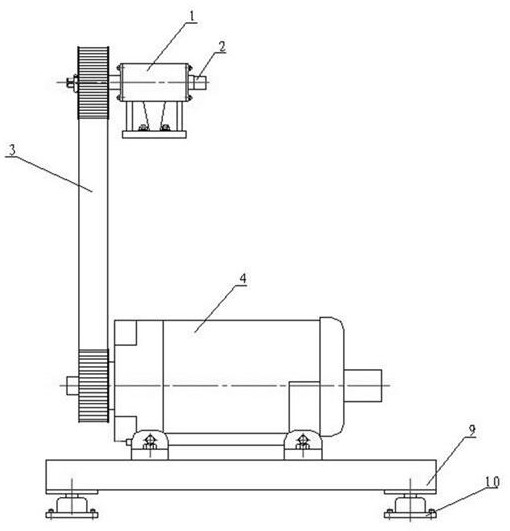
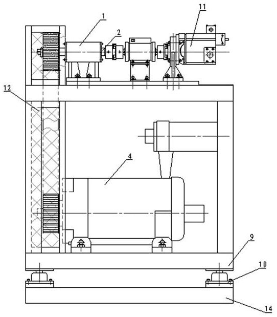
[0026]Refer to the attachmentfigure 1 ,2, A high-speed hydraulic oil pump floor drive structure, the high-speed rotating shaft 2 on the high-speed spindle lubrication box 1 is connected to the synchronous tooth strip 3, the other end of the synchronous toothed belt 3 is connected to the DC motor 4 through the motor speed disk 6, the DC motor 4 passes the motor The adjustment frame 7 is mounted on the mounting frame 9.

[0027]The lower end of the mounting frame 9 is mounted with a damping block 10. One end of the high-speed rotary shaft 2 has a fuel pump speed disk 5. The motor regulator 7 is fixed to the mounting frame 9 by the motor conditioning screw 8.

Embodiment 2

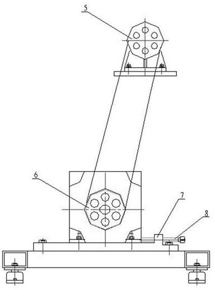
[0029]Refer to the attachmentimage 3 ,4The aircraft hydraulic oil pump provides power to the aircraft hydraulic system. At 1500 ~ 4200R / min speed, the mutual settlement of landing, the flight task profile, etc., the hydraulic system load has a sharp change, and the drive system of the hydraulic oil pump A large influence, the rotational speed changes dramatically, and the impact is eliminated in the ground simulation test of the aircraft hydraulic system.

[0030]The aircraft hydraulic pump 11 is a constant voltage variable plunger pump, a rated pressure 21MPa, a maximum flow of 92.5 L / min, its maximum output power:

[0031]

[0032]Oil pump input power:

[0033]

[0034]In order to ensure that the drive motor has a certain load stiffness on the load oil pump, the drive motor power is pressed:

[0035]PElectricity = KPEntered= 1.5x36 = 54KW

[0036]Where: K - power margin coefficient is generally selected from 1.5 to 2.0, and 1.5 is taken here.

[0037]Therefore, the motor output power is selected from...

Embodiment 3

[0048]A high-speed hydraulic oil pump ground driving method, the method modulates the input current of the DC motor 4, thereby changing the output speed of the DC motor, transmitting the power of the DC motor 4 by the synchronous tooth strip 3, changing the oil pump speed disk 5, motor speed The diameter of the disk 6 is thereby adjusted the transfer speed of the DC motor to the hydraulic oil pump;

[0049]Pump speed disk 5 Connect high speed shaft 2, high speed rotary shaft 2 connecting hydraulic oil pump, high-speed spindle lubrication box 1 to lubricate high-speed rotary shaft 2;

[0050]The DC motor 4 is mounted on the motor regulator 7, moving the DC motor via the motor conditioning screw 8 to adjust the preload of the synchronous toothed belt 3 to ensure that it is not slipping;

[0051]Motor adjustment frame 7, the DC motor 4 is mounted on the mounting frame 9, and the mounting frame 9 is shocked through the entire system through the damper block 10.

[0052] Further, the drive garace 14...


PUM


Abstract

The invention relates to a high-speed hydraulic oil pump ground driving structure and a driving method thereof, belongs to a hydraulic oil pump driving technology, and particularly relates to a mode that a direct-current motor stably transmits motor power to a hydraulic oil pump through a synchronous toothed belt. According to the invention, a high-speed rotating shaft on a high-speed rotating shaft lubricating box is connected with a synchronous toothed belt, the other end of the synchronous toothed belt is connected with a direct-current motor through a motor rotating speed disc, and the direct-current motor is installed on an installation frame through a motor adjusting frame; the speed regulation precision is improved, and the speed regulation range is wider; the processing cost is low, the process requirement is simple, and repair and maintenance are easy; and the rate is high, the rotating speed characteristic is good, and the rotating speed can be stabilized at a given instruction value at a very high speed.

Description

Technical field[0001]The present invention relates to a high-speed hydraulic oil pump ground drive structure and a driving method thereof, which is a hydraulic oil pump driving technology, and more particularly to a DC motor to pass the motor power to the hydraulic oil pump by a synchronous toothed strip.Background technique[0002]The aircraft's hydraulic oil pump is driven by aircraft engine in actual use, and the power of the oil pump is relatively small. The aircraft is substantially constant in a certain flight or full-load operation in a particular flight. The ground simulation aircraft oil pump drive is used by a rotating machine instead of the engine. The power of the drive device is far without the aircraft engine, resulting in a larger speed difference between the oil pump airborne in the ground test and the full load of the rotating machine, affecting the hydraulic system the work. Here, a DC motor is provided by a synchronous toothed tape to smooth the motor power to the h...

Claims


Application Information

Patent Timeline
Patent Type & Authority Applications(China)
IPC IPC(8): H02K7/10H02K5/26H02K5/24H02P7/06F04B17/03F04B53/00
CPCH02K7/1008H02K5/26H02K5/24H02P7/06F04B17/03F04B53/00
Inventor 王小峰王宝亮杨志艺刘波刘渊沈福红罗敏杨旭张立圣
Owner JIANGXI HONGDU AVIATION IND GRP
Why Eureka
Try Eureka