
Easily adjustable speed change device

A variable speed device and variable speed adjustment technology, which is applied to hoisting devices, transmission devices, portable lifting devices, etc., can solve the problems of complex speed changing process, and achieve the effects of high speed regulation accuracy, simple structure and good application prospects.

Inactive Publication Date: 2020-09-08
常金丽
View PDF0 Cites 3 Cited by
  • Summary
  • Abstract
  • Description
  • Claims
  • Application Information

AI Technical Summary

Problems solved by technology

[0003] As far as the present is concerned, the shifting process of the existing infinitely variable speed is relatively complicated when it is used, and it is difficult to meet the needs of the existing life and production, and then a speed change device that is easy to adjust is proposed

Method used


Image

  • Easily adjustable speed change device
  • Easily adjustable speed change device
  • Easily adjustable speed change device

Examples


Embodiment 1

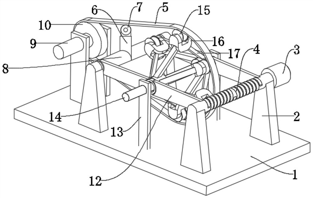
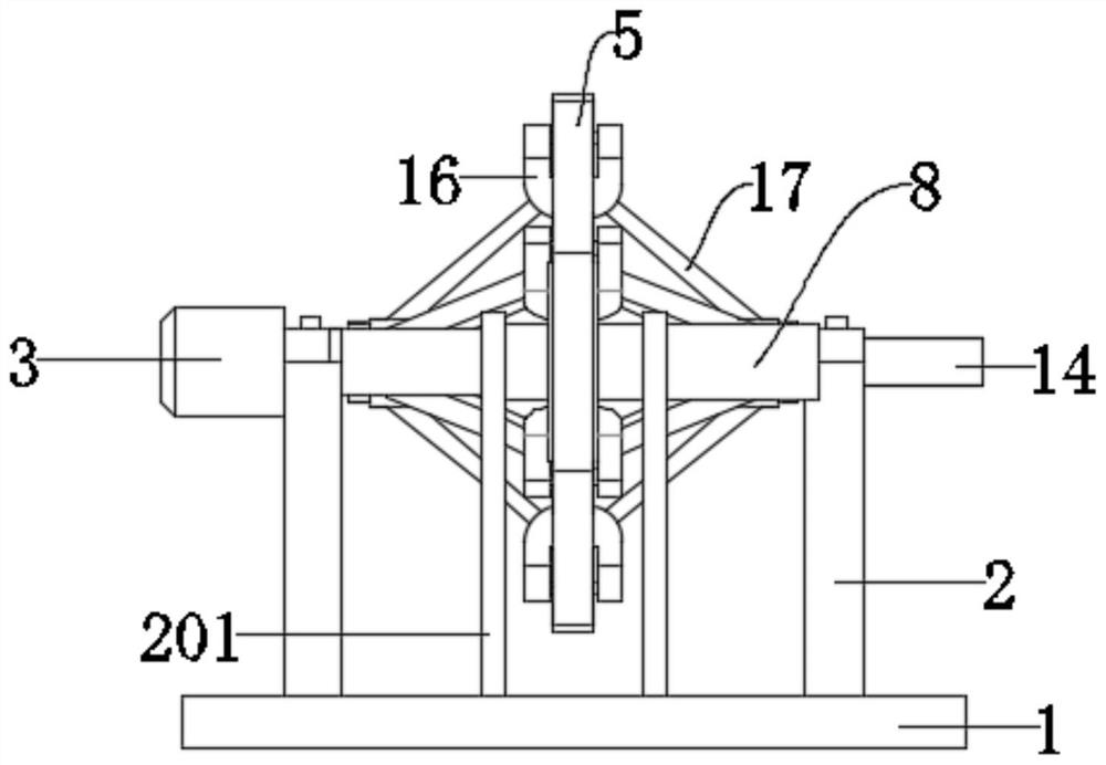
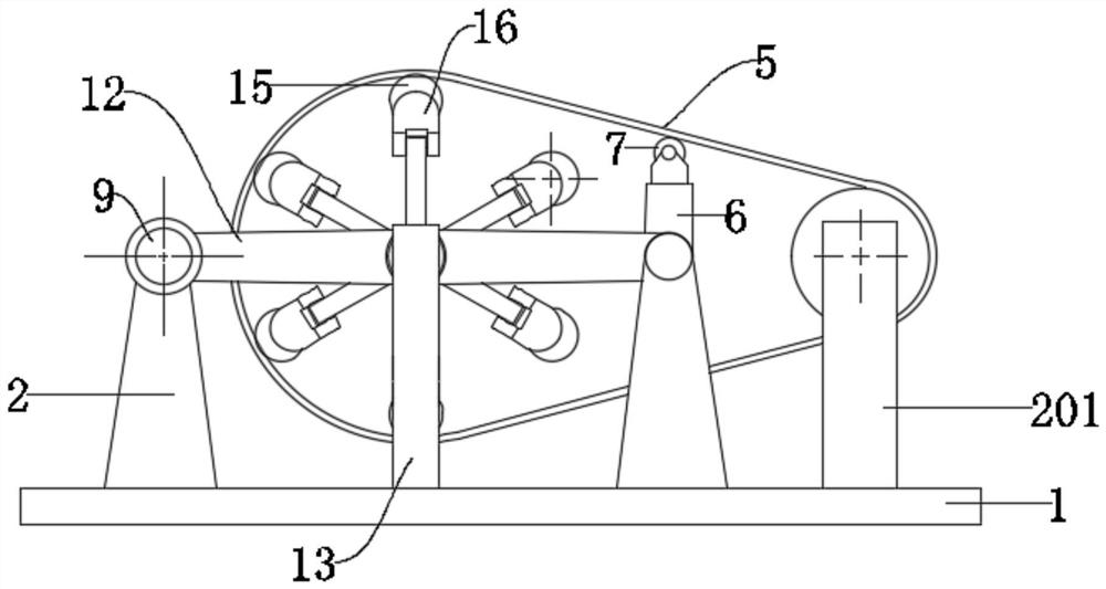
[0022] see Figure 1-4 , an easy-to-adjust speed change device, including a base plate 1, an input shaft 9 and an output shaft 14, the input shaft 9 and the output shaft 14 are respectively used for power input and output; between the input shaft 9 and the output shaft 14 A speed change adjustment assembly is arranged between them, and the speed change adjustment assembly is used for adjusting the transmission ratio between the input shaft 9 and the output shaft 14, thereby changing the power output of the output shaft 14; the speed change adjustment assembly includes a limit shaft 141, a connecting Rod 17, hinged slide block 18, hinged block 16, transmission belt 5, rotating wheel 15 and driving device, two brackets 13 are fixedly connected on the described bottom plate 1, and described limiting rotating shaft 141 is installed on the bracket two 13 in rotation Between, the output shaft 14 is fixedly connected with the limiting rotating shaft 141; the limiting rotating shaft 1...

Embodiment 2

[0030] This embodiment has made the following improvements on the basis of Embodiment 1. The improvement is that the transmission belt 5 is a gear belt, and the driving wheel 10, the crown wheel 7 and the rotating wheel 15 are equipped with gear teeth. , through the configuration of the gear belt 5, the accuracy of the transmission is further improved.

[0031] The working principle of this embodiment: by laying the transmission belt 5 as a gear belt, and the driving wheel 10, the crown wheel 7 and the running wheel 15 are equipped with gear teeth, and the gear belt 5 is arranged to further improve the transmission. accuracy.


PUM


Abstract

The invention discloses an easily adjustable speed change device. The easily adjustable speed change device comprises a baseplate, an input shaft and an output shaft, wherein a speed change adjustingcomponent is arranged between the input shaft and the output shaft; articulated sliding blocks are slidably arranged on a limiting rotating shaft and are matched with limiting grooves in a sliding manner; the two groups of articulated sliding blocks are symmetrically laid on the limiting rotating shaft; hanging loops are fixedly connected to the articulated sliding blocks; connecting rods are articulated on the hanging loops; the other ends of the connecting rods are articulated on articulated blocks; the connecting rods on the same side are articulated on the same articulated block; rotatingwheels are articulated on the tops of the articulated blocks; a driving belt is arranged on the rotating wheels in a tensioning manner; the other end of the driving belt is connected to the output shaft; and a driving device is arranged on the baseplate and is connected to the articulated sliding blocks. The easily adjustable speed change device has a simple structure and strong practicability; the articulated sliding blocks are driven to move, and the rotating radius of the rotating wheels changes, so that the transmission ratio between the output shaft and the input shaft changes, and the speed adjustment is further realized. The easily adjustable speed change device has high speed regulation accuracy and good application prospect.

Description

technical field [0001] The invention relates to the field of transmissions, in particular to an easily adjustable transmission. Background technique [0002] The transmission is a mechanism used to change the speed and torque from the engine. It can change the transmission ratio of the output shaft and the input shaft in fixed or stepwise steps, also known as the gearbox. Speed ​​changer is made up of speed change transmission mechanism and operating mechanism. There are two types of transmissions: stepped transmission and continuously variable transmission. The stepped transmission is the most widely used one. It adopts gear transmission and has several fixed-value transmission ratios; stepless transmission refers to a transmission system that can continuously obtain any transmission ratio within the transmission range. The best match between the drive train and the engine operating conditions can be obtained through continuously variable transmission. [0003] As far as...

Claims


Application Information

Patent Timeline
Patent Type & Authority Applications(China)
IPC IPC(8): F16H37/12F16H55/36F16H55/17
CPCF16H37/124F16H55/171F16H55/36F16H2037/128
Inventor 常金丽
Owner 常金丽
Learn More