
Three-phase single-section/double-section multiple-pole switching reluctance motor

A technology of switched reluctance and electric motors, which is applied in the direction of electrical components, electromechanical devices, and static components of magnetic circuits, etc. It can solve the problems of no progress in switched reluctance motors, lagging industrialization and applied research work, etc., and achieve easy heat dissipation , The effect of increasing the magnetic energy area and reducing the heat load

Inactive Publication Date: 2013-01-30
张世清
View PDF1 Cites 2 Cited by
  • Summary
  • Abstract
  • Description
  • Claims
  • Application Information

AI Technical Summary

Problems solved by technology

[0007] At present, all countries in the world are researching the new type of motor, the switched reluctance motor. There have been great breakthroughs in the control technology using single-chip microcomputer control technology and the modularization of application-specific integrated circuits, but the industrialization and application research work is relatively lagging behind. , especially for switched reluctance motors per se

Method used


Image

  • Three-phase single-section/double-section multiple-pole switching reluctance motor
  • Three-phase single-section/double-section multiple-pole switching reluctance motor
  • Three-phase single-section/double-section multiple-pole switching reluctance motor

Examples


Embodiment Construction

[0042] Below in conjunction with accompanying drawing and embodiment the present invention will be further described

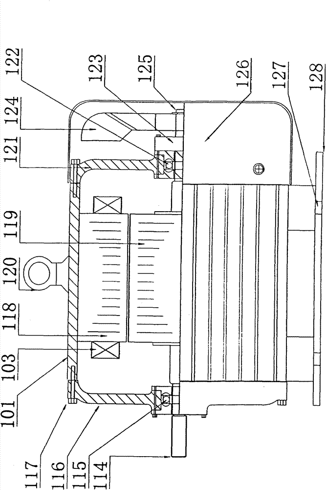
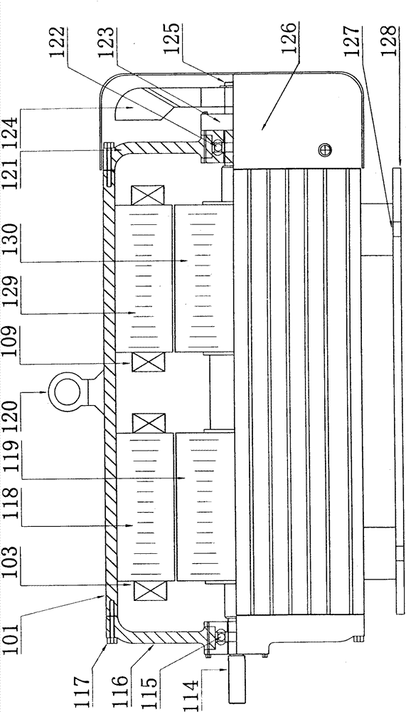
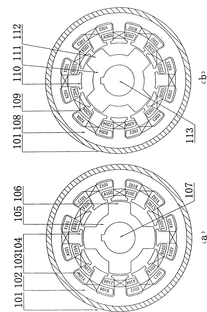
[0043] refer to figure 1 , a three-phase single-stage double-pole switched reluctance motor in the figure, including a motor housing 101 placed on a motor base 128, a motor suspension ring 120 is provided in the middle of the motor housing 101, a motor front end cover 116 and a motor rear end cover 121 respectively It is arranged at both ends of the motor shaft 114, and a rotor is arranged between the motor front end cover 116 and the motor rear end cover 121. The motor rear end cover 121 is provided with a motor fan cover 126, and a motor fan is arranged inside the motor fan cover 126. 124, an electronic sensor 123 is arranged between the motor rear end cover 121 and the motor fan 124, and the motor is further composed of a double salient pole structure stator and rotor formed by laminating silicon steel sheets; its stator core includes the first section of s...


PUM


Abstract

The invention relates to a three-phase single-section / double-section multiple-pole switching reluctance motor. A casing of the motor is arranged on a base, the middle part of the casing is provided with a hanging ring of the motor, a front end cover and a back end cover are respectively arranged at both ends of a rotating shaft, rotors are arranged between the front end cover and the back end cover, an air cover is arranged outside the back end cover, a fan is arranged in the air cover, and a sensor is arranged between the back end cover and the fan or between the back end cover and a second-section rotor; the motor comprises stators and the rotors with a structure of double convex poles, also comprises one section or two sections and can run by a single section or double sections; the iron cores of the stators and the rotors both comprise a single section or two sections, and the lengths and the diameters of the iron cores of the two sections of the stators and the rotors are equal; two sets of concentrated windings or sandwich windings are respectively arranged on two sections of stator teeth, and armature windings on two teeth of the same phase of each set of windings are connected in series or in parallel to form one phase; the magnetic poles of the two sections of stators are aligned, and the difference of the magnetic poles of the two sections of rotors is 1 / 2 of a rotor polar distance angle; or, the magnetic poles of the two sections of rotors are aligned, and the difference of the magnetic poles of the two sections of stators is 1 / 2 of a stator polar distance angle; and the invention has the characteristics of high efficacy, high starting torque, easy control and low cost.

Description

technical field [0001] The invention relates to a three-phase single-stage double-pole switched reluctance motor, in particular to a three-phase single-stage and double-stage double-pole switched reluctance motor. Background technique [0002] At present, the switched reluctance motor is a double-salient switching motor, and its stator poles are wound with concentrated windings; the motor can be divided into single-phase, three-phase, and four-phase switched reluctance motors according to the number of phases, and the three-phase 6 / 4, 12 / 8, and four-phase 8 / 6 structures are the majority. Switched reluctance motors have simple structure, easy manufacturing, easy speed regulation, reliable operation, not easy to damage, high power factor, high operating efficiency, large starting torque, It has the advantages of small starting current, strong overload capacity, heavy load starting, etc., and has good performance in a wide range of high-speed constant power range. [0003] Wit...

Claims


Application Information

Patent Timeline
Patent Type & Authority Patents(China)
IPC IPC(8): H02K29/06H02K16/00H02K1/12
Inventor 张世清张红梅
Owner 张世清
Learn More