Detachable vibration reduction gear

A technology of gears and damping grooves, applied in belts/chains/gears, components with teeth, portable lifting devices, etc. The effect of generalization, high practical value and simple structure

Active Publication Date: 2015-04-29
YANCHENG INST OF TECH
View PDF10 Cites 25 Cited by
  • Summary
  • Abstract
  • Description
  • Claims
  • Application Information

AI Technical Summary

Problems solved by technology

[0003] The purpose of the present invention is to solve the problem that the gear teeth of the integrated structure gear in the prior art lose its use value after the teeth are damaged, and the replacement of the entire gear may cause great economic losses, and the detachable gear in the prior art has low precision and large vibration. To solve the problem, provide a detachable damping gear with simple structure and

Method used


Image

  • Detachable vibration reduction gear
  • Detachable vibration reduction gear
  • Detachable vibration reduction gear

Examples


Embodiment 1

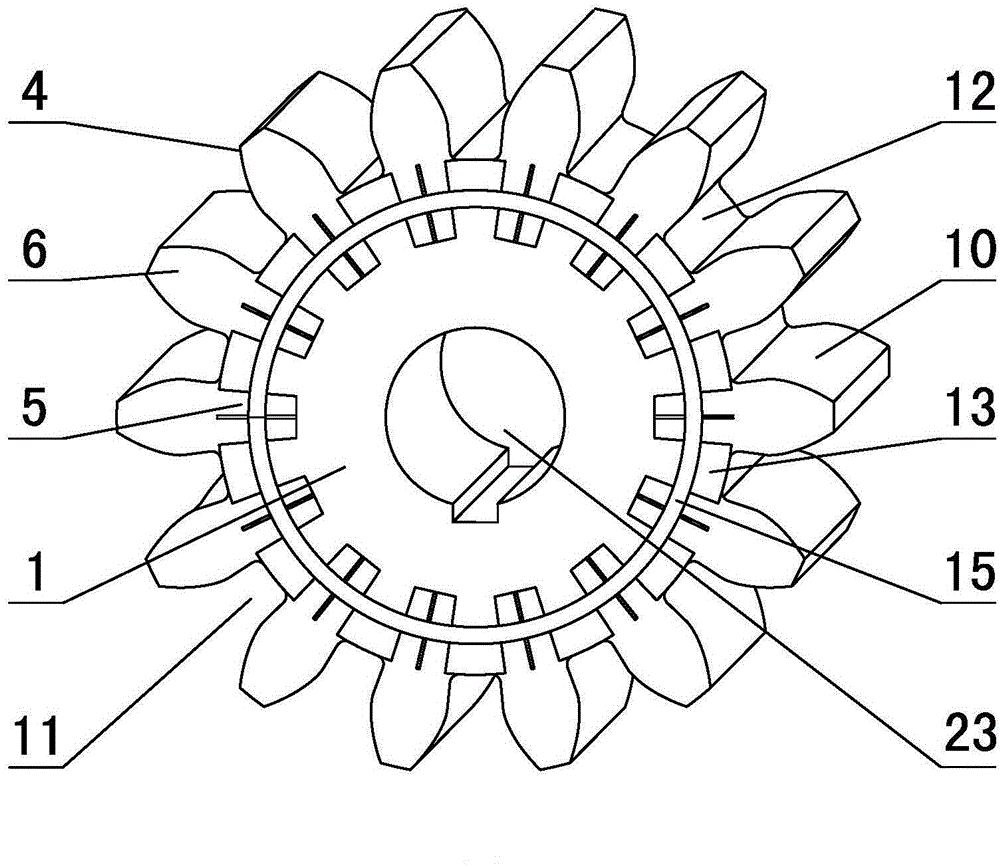
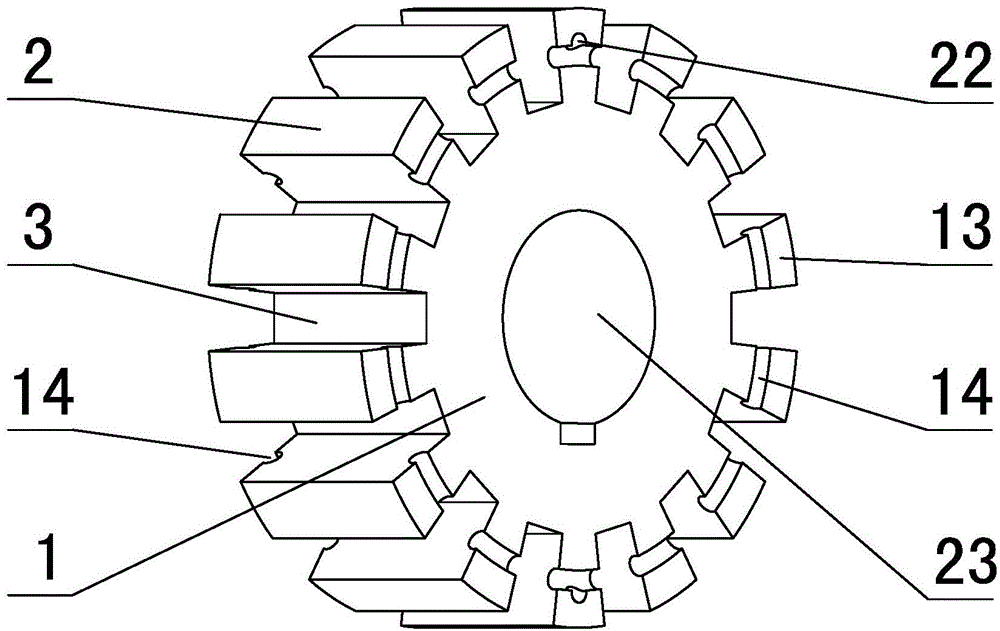
[0025] in such as figure 1 In the shown embodiment 1, a detachable damping gear is provided with 14 gear teeth, and the center of the gear is provided with a shaft hole 23, and the detachable damping gear includes a base wheel 1 (see image 3 ), the diameter of the base wheel is equal to the diameter of the root circle of the gear with the basic modulus of 6 (that is, the diameter of the root circle of the gear with the number of teeth 14 and the modulus of 6), and the upper edge of the base wheel is evenly There are axial through grooves 3 with the same number as the number of gear teeth. The opening width of the through grooves is greater than the width of the bottom of the through grooves. The angle between the side walls on both sides of the through grooves is 6 degrees. Embedded with a detachable gear tooth 4 whose tooth width is consistent with the length of the through groove, the detachable gear tooth and the base wheel form a complete gear, and the detachable gear too...

Embodiment 2

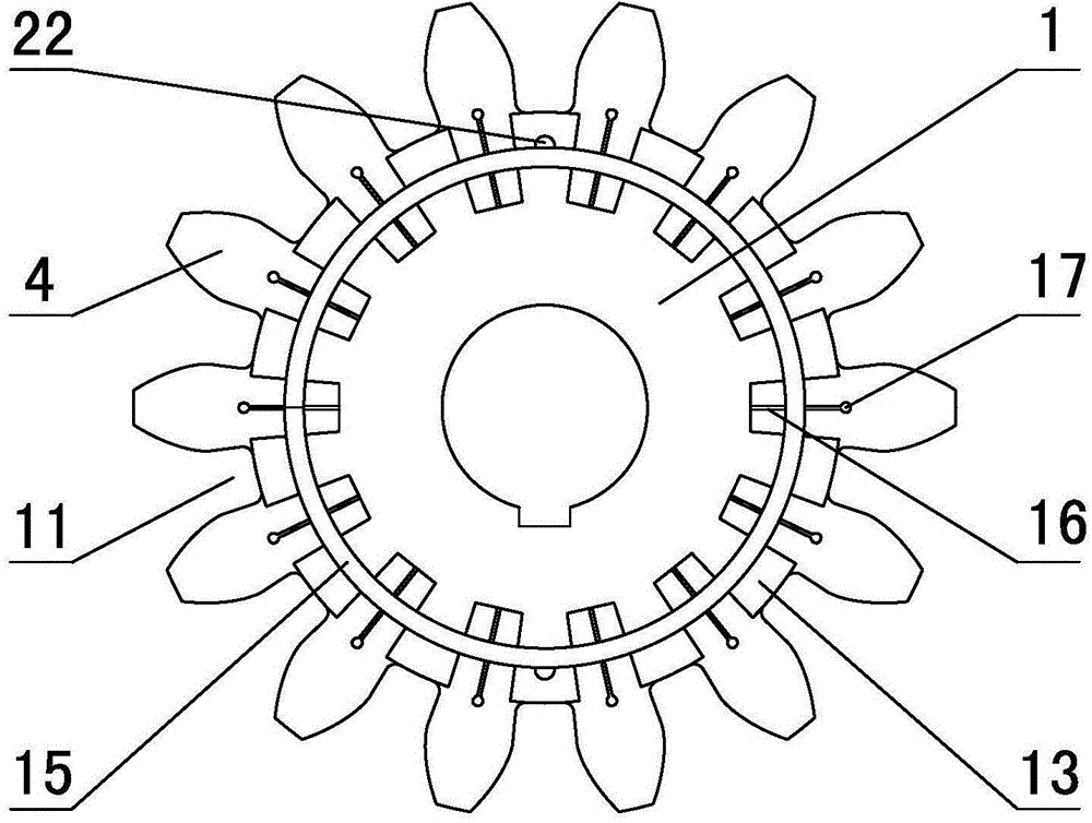
[0027] exist figure 2 In the shown embodiment 2, the angle between the side walls on both sides of the through groove is 3 degrees, the cross section of the vibration damping groove is rectangular, and the bottom of the vibration damping groove expands to form a cylindrical buffer chamber 17 in cross section. , the width of the damping groove is 10% of the bottom width of the through groove, and the diameter of the cylindrical buffer cavity is 1.5 times the width of the damping groove. Embodiment 2 The cross-section of the fan-shaped ring-shaped fixing groove on the two end faces of the stopper is a circular segment shape greater than a semicircle (see Figure 6 ), the notch width of the fan ring fixing groove is slightly smaller than the maximum width of the fixing groove (that is, the notch width is slightly smaller than the diameter of the fixing bar), and the cross section of the circular fixing bar is adapted to the cross section of the fixing groove , the ring-shaped f...

Embodiment 3

[0029] exist Figure 9 In the shown embodiment 3, the number of teeth of the gear is 14, and the gear module is 8, which is larger than the basic module of embodiment 1. The tooth head bump on the gear teeth is formed with a flat surface at the end of the extension direction. The side walls of the structure face 18 (see Figure 7 ), the upper surface of the tooth head bump is smoothly connected with the tooth profile curved surface of the detachable gear tooth, forming half of the groove bottom surface of the detachable vibration-damping gear tooth groove, and the side wall surface is on the axial center surface of the detachable vibration-damping gear The opposite side walls of two adjacent detachable gear teeth are in close contact with each other, and the upper surfaces of the protrusions of the tooth heads are smoothly connected to form a complete groove bottom surface of the tooth groove of the detachable damping gear. The included angle between the side walls on both si...


PUM

PropertyMeasurementUnit
Angleaaaaaaaaaa

Abstract

The invention discloses a detachable vibration reduction gear, which comprises a basic wheel, wherein the diameter of the basic wheel is not greater than the diameter of a tooth root circle of the gear with a specified basic modulus; axial through slots with the number being the same as the number of gear teeth are formed in the basic wheel; detachable wheel teeth are respectively embedded in the through slots, and comprise tenon bodies inserted in the through slots and tooth heads integrally connected with the tenon bodies; end parts, close to the tenon bodies, of the tooth heads extend to two sides to form tooth head bumps; the lower surfaces of the tooth head bumps are arc faces adapting to the external circular surface of the basic wheel; the upper surfaces of the tooth head bumps are in smooth connection with the tooth profile curved surfaces of the detachable wheel teeth to form part of slot bottom faces of gear tooth slots; wheel tooth fixing slots are formed in gear wheel surfaces; circular ring shaped fixing bars are embedded in the fixing slots; vibration reduction slots are also formed in the tenon bodies of the detachable wheel teeth. The detachable vibration reduction gear provided by the invention not only is simple in structure and convenient for replacing the wheel teeth so as to reduce economic loss, but also can realize the universalization of a gear main body structure and has higher practical value.

Description

technical field [0001] The invention relates to the technical field of gear transmission, in particular to a detachable damping gear. Background technique [0002] Gear mechanism is the most widely used transmission mechanism in modern machinery. Gear transmission is an important part of mechanical transmission. It plays the role of transmitting power and motion. With the advantages of mature technology and other advantages, transmission gears are widely used in machine and instrument manufacturing industries. In various heavy-duty institutions, gears are often needed to provide the power required for mechanical operation, and these gears are huge and expensive, and the gears will also suffer some fatal damage during the day and night work, such as: tooth surface wear; tooth surface Pitting, spalling, cracking of the carburized layer on the tooth surface; corrugation on the tooth surface, ribbing on the tooth surface, gluing on the tooth surface, and plastic deformation on ...

Claims


Application Information

Patent Timeline
IPC IPC(8): F16H55/17
CPCF16H55/08F16H55/17
Inventor 刘富豪张雁聪龚苏阳蒋汉军朱龙英
Owner YANCHENG INST OF TECH
Why Eureka
Try Eureka