Pipe installing support, module of pipe installing support and micro-channel heat exchanger installing system
A technology for installing brackets and pipelines. It is applied to pipeline brackets, heat exchanger shells, lighting and heating equipment, etc. It can solve the problems of pipeline safety, hidden dangers, and damage to pipeline substrates, so as to ensure the reliability of use, The effect of avoiding damage and eliminating potential safety hazards
- Summary
- Abstract
- Description
- Claims
- Application Information
AI Technical Summary
Problems solved by technology
Method used
Image

Examples
Embodiment Construction
[0023] The embodiments of the present invention will be described in detail below with reference to the accompanying drawings, but the present invention can be implemented in many different ways defined and covered by the claims.
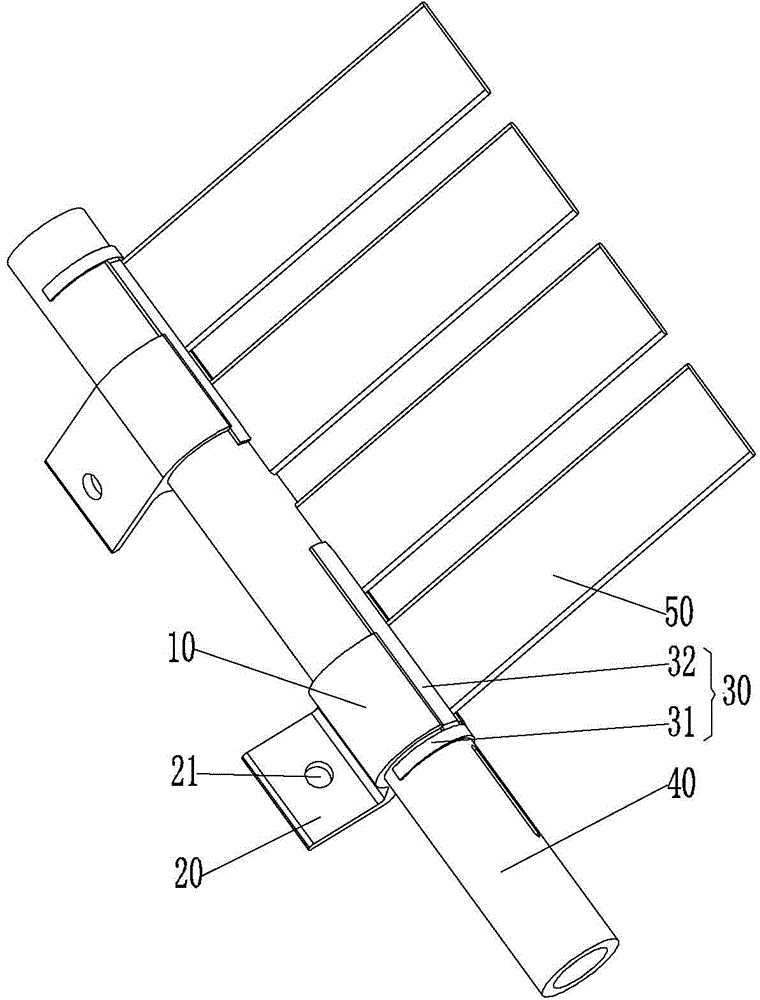
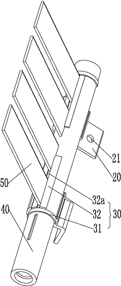
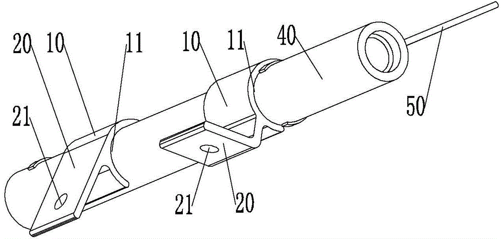
[0024] As a first aspect of the present invention, a pipe installation bracket is provided. Such as Figure 1 to Figure 6 As shown, the pipe installation bracket includes a body 10, and the body 10 has a clamping portion 11 for connecting the pipe. Since the pipeline installation bracket is connected to the pipeline by clamping, the pipeline installation bracket will not damage the base material of the pipeline, thereby avoiding damage to the pipeline during subsequent use, eliminating potential safety hazards, and ensuring the safety of the pipeline. use reliability. At the same time, the pipe installation bracket in the present invention has the characteristics of simple structure and low manufacturing cost.
[0025] The clamping part 11 in the...
PUM
 Abstract
Description
Claims
Application Information
 - R&D
- Intellectual Property
- Life Sciences
- Materials
- Tech Scout
- Unparalleled Data Quality
- Higher Quality Content
- 60% Fewer Hallucinations
Browse by: Latest US Patents, China's latest patents, Technical Efficacy Thesaurus, Application Domain, Technology Topic, Popular Technical Reports.
© 2025 PatSnap. All rights reserved.Legal|Privacy policy|Modern Slavery Act Transparency Statement|Sitemap|About US| Contact US: help@patsnap.com