Blast hole plugging device and method

A technology for plugging devices and blastholes, which is applied in blasting and other directions, and can solve problems such as poor blasting effect and short action time of blasting gas

Inactive Publication Date: 2015-04-29
北京安赢堡科技发展有限公司
View PDF5 Cites 2 Cited by
  • Summary
  • Abstract
  • Description
  • Claims
  • Application Information

AI Technical Summary

Problems solved by technology

[0004] The object of the present invention is to provide a blasthole plugging device and method to overcome the s

Method used


Image

  • Blast hole plugging device and method
  • Blast hole plugging device and method
  • Blast hole plugging device and method

Examples


Embodiment 1

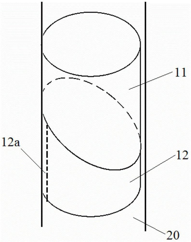
[0052] The blasthole 20 is a circular hole, and its diameter is 89mm. Correspondingly, the first plugging part 11 and the second plugging part 12 are cylindrical, and its diameter is 75-80mm. The height of the blasthole plugging device (here The "height of the blast hole plugging device" refers to the height of the first plugging part 11 and the second plugging part 12 when the first plugging part 11 and the second plugging part 12 form surface contact with each other through the first surface and the second surface The overall height of part 12) is 60mm, the included angle between the first surface and the axis of the blasthole 20 and the included angle between the second surface and the axis of the blasthole 20 are both 22°, the diameter of the through hole 13 is 10mm, when When the cross section of the first groove 12 a of the second blocking portion 12 is a semicircle, its diameter is 28 mm or the like.

[0053] When the blasthole 20 is inclined upwards ("upward" here refe...

Embodiment 2

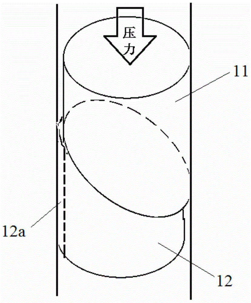
[0055] The blasthole 20 is a circular hole, and its diameter is 89mm. Correspondingly, the first plugging part 11 and the second plugging part 12 are cylindrical, and its diameter is 75-80mm. The height of the blasthole plugging device (here The "height of the blast hole plugging device" refers to the height of the first plugging part 11 and the second plugging part 12 when the first plugging part 11 and the second plugging part 12 form surface contact with each other through the first surface and the second surface The overall height of part 12) is 60mm, the included angle between the first surface and the axis of the blasthole 20 and the included angle between the second surface and the axis of the blasthole 20 are 18°, the diameter of the through hole 13 is 10mm, when When the cross section of the first groove 12 a of the second blocking portion 12 is a semicircle, its diameter is 28 mm or the like.

[0056] When the blasthole 20 is inclined downwards ("downward" here refer...


PUM


Abstract

The invention discloses a blast hole plugging device and method. The blast hole plugging device comprises a first plugging part and a second plugging part, wherein the second plugging part is near a blast hole opening and is fixed with the inner wall of a blast hole, the circumferential profile of the first plugging part and the circumferential profile of the second plugging part are matched with the hole diameter of the blast hole, the first plugging part is provided with a first surface forming an angle with the axial line of the blast hole, the second plugging part is provided with a second surface forming an angle with the axial line of the blast hole, and the first plugging part and the second plugging part mutually form surface contact through the first surface and the second surface. In the blasting process, the first plugging part moves along the second surface due to the pressure of detonation gas in the blast hole, i.e., the first plugging part and the second plugging part generate relative malposition, the first plugging part exerts the positive pressure on the inner wall of the blast hole, and the pressure of the detonation gas is greater, so the generated friction is also greater, and the moving of the first plugging part and the second plugging part towards the outer part of the blast hole is retarded through the friction force, so that the acting time of the detonation gas is increased, and a good blasting effect is achieved.

Description

technical field [0001] The invention relates to the field of deep hole blasting, in particular to a blast hole sealing device and method. Background technique [0002] Deep hole blasting technology is often used in coal mines. For example, deep hole blasting is used in the forced caving of roofs in coal mines, pressure relief blasting of super long deep holes in roadways, or stress relief in tunnels to relieve stress concentration. The key to deep hole blasting is the effect of blast hole sealing, especially for pre-split blasting of ultra-deep holes over 30 meters. The amount of internal charge is relatively large, and only when the blast hole is completely blocked can the action time of the blasting gas be increased, thereby obtaining a better pre-splitting blasting effect. [0003] Traditionally, blasting mud is usually used to seal blastholes, but because blasthole mud only relies on its friction with the blasthole wall to block blasting gas, during the blasting process...

Claims


Application Information

Patent Timeline
IPC IPC(8): F42D1/18
Inventor 宋俊生
Owner 北京安赢堡科技发展有限公司
Why Eureka
Try Eureka