
Main reflection point area determining method of antenna measurement darkroom

A technology for determining the main reflection point and area, which is applied in the direction of measuring devices and instruments, can solve the problems of not being able to quickly and effectively find the main reflection area of ​​the test area, waste of resources, etc., and achieve the reduction of the main reflection point area, saving the proportion, and reasonable The effect of laying out the way

Inactive Publication Date: 2015-04-29
BEIJING INST OF RADIO METROLOGY & MEASUREMENT
View PDF4 Cites 4 Cited by
  • Summary
  • Abstract
  • Description
  • Claims
  • Application Information

AI Technical Summary

Problems solved by technology

[0005] An object of the present invention is to provide a method for determining the main reflection point area of ​​an antenna measurement darkroom, to solve the problem that the current prior art cannot quickly and effectively find the test area in the main reflection area of ​​the darkroom, and effectively suppress the reflected signal in the main reflection area , and the large-scale laying of absorbing materials causes the problem of waste of resources

Method used

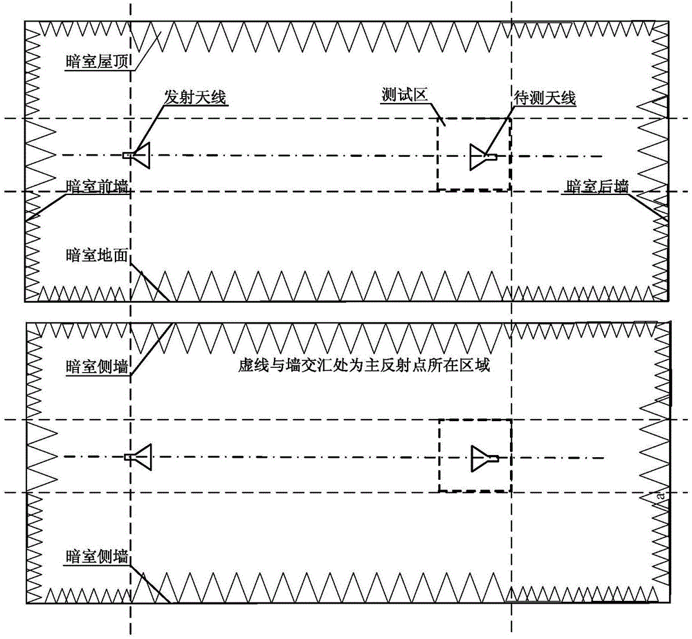

Image

  • Main reflection point area determining method of antenna measurement darkroom
  • Main reflection point area determining method of antenna measurement darkroom
  • Main reflection point area determining method of antenna measurement darkroom

Examples


Embodiment Construction

[0027] In order to illustrate the present invention more clearly, the present invention will be further described below in conjunction with preferred embodiments and accompanying drawings. Similar parts in the figures are denoted by the same reference numerals. Those skilled in the art should understand that the content specifically described below is illustrative rather than restrictive, and should not limit the protection scope of the present invention.

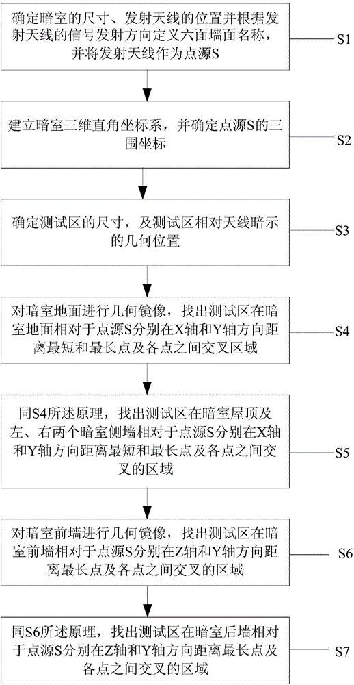
[0028] Such as figure 2 As shown, the present invention discloses a method for determining the main reflection point area of ​​an antenna measurement darkroom, the method comprising:

[0029] S1. Taking the signal transmitting direction of the transmitting antenna as the reference direction, define the six walls of the antenna measurement darkroom located in front, rear, left, right, up and down of the transmitting antenna as the back wall of the darkroom, the front wall of the darkroom, and the side wall of the left dark...


PUM


Abstract

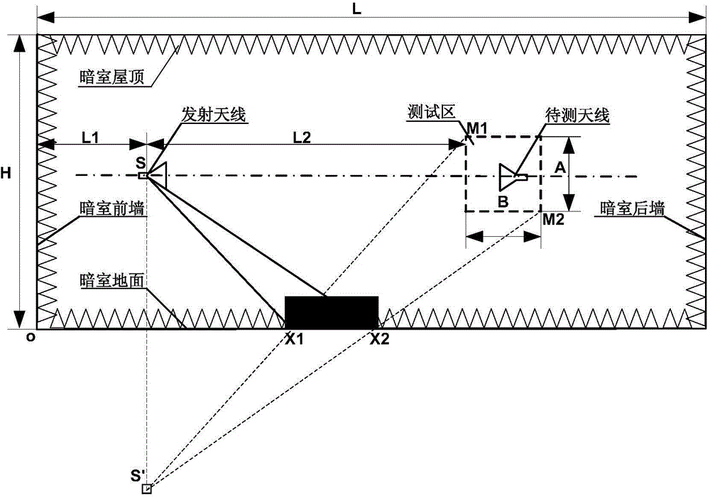
The invention discloses a main reflection point area determining method of an antenna measurement darkroom. The method comprises steps as follows: a transmitting antenna in the darkroom is used as a point source, each surface in the darkroom is used as a mirror surface, geometric mirroring is performed on the point source and all the mirror surfaces, and a mirror point of each surface is obtained; each position of a test area of the darkroom is connected with the mirror point of each surface, and an intersectional area of each connecting line and each surface is obtained on each surface; the intersectional area on each surface is used as a main reflection point area of the test area of the darkroom on each surface of the darkroom. With the adoption of the method, the main reflection point areas of the test area on all walls can be determined accurately, and waste of wave-absorbing materials can be reduced.

Description

technical field [0001] The present invention designs a method for determining the reflection point area. More specifically, it relates to a method for determining the main reflection point area of ​​an antenna measurement darkroom. Background technique [0002] With the increasingly serious electromagnetic environment interference problem in the outdoor test field, the microwave anechoic chamber has become a typical place for indoor antenna performance measurement. The performance design of the anechoic chamber is an important factor affecting the measurement accuracy of the antenna performance. With the laying of absorbing materials, the microwave anechoic chamber can provide a stable and controllable electromagnetic signal environment that meets the requirements of antenna measurement. The rational layout of the absorbing material is an important guarantee to ensure the performance of the microwave anechoic chamber. The function of the absorbing material is to reduce the ...

Claims


Application Information

Patent Timeline
Patent Type & Authority Applications(China)
IPC IPC(8): G01B21/00
CPCG01B21/00
Inventor 马永光杨金涛王淞宇韩玉峰
Owner BEIJING INST OF RADIO METROLOGY & MEASUREMENT
Learn More