
Near-surface tomographic velocity analysis method

A velocity analysis and surface technology, applied in the field of seismic physical exploration, can solve problems such as the difficulty of iterative inversion of initial velocity modeling, and achieve the effect of real and reliable calculation results, strong stability, and obvious geophysical significance

Inactive Publication Date: 2015-04-29
CHINA PETROLEUM & CHEM CORP +1
View PDF3 Cites 19 Cited by
  • Summary
  • Abstract
  • Description
  • Claims
  • Application Information

AI Technical Summary

Problems solved by technology

However, compared with ray tomography, there is often a very strong nonlinear relationship between the velocity disturbance and the objective function in wave equation tomography, which requires a high-precision initial velocity model, which is necessary for initial velocity modeling and iterative inversion great difficulty

Method used


Image

  • Near-surface tomographic velocity analysis method
  • Near-surface tomographic velocity analysis method
  • Near-surface tomographic velocity analysis method

Examples


Embodiment 1

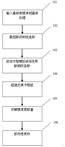
[0039] Example 1. Such as figure 1 Shown, a kind of near-surface tomographic velocity analysis method is characterized in that, the method comprises the steps:

[0040] In step 101, input parameter data into conventional processing software, including original running records, observation system and other information, and obtain the real first arrival travel time. The process goes to step 102.

[0041] In step 102, according to the initial velocity model obtained in step 101, the shortest path ray tracing is performed to obtain the travel time of the model, and the travel time residual is obtained. The process goes to step 103.

[0042] In step 103, according to the initial velocity model obtained in step 101, the wave field is simulated by the wave equation to obtain the kernel function. The wave equation is a frequency domain wave equation, and the sensitive kernel function obtained is as follows Figure 4 shown. The flow goes to step 104 .

[0043] In step 104, accor...

Embodiment 2

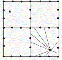
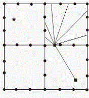
[0047]Example 2. The difference between this embodiment and Implementation 1 is that: in step 101, the input parameter data in the conventional processing software also includes relevant information such as the excitation point and the elevation of the receiving point; in step 102, when performing shortest path ray tracing, the Calculate the range of the first Fresnel zone when the forward and reverse travel is calculated with the shot point and the receiver point as the excitation point. In step 103, the sensitive kernel function is the Frechet kernel function defined by the first Fresnel band (results such as image 3 a to image 3 As shown in c) the specific expression for calculating the kernel function through the frequency wave equation is:

[0048] F T ( r , ω ) = - 2 ω ...


PUM


Abstract

The invention discloses a near-surface tomographic velocity analysis method. The near-surface tomographic velocity analysis method comprises the following steps: picking up travel time of first arrival by aiming at pre-stack data, and obtaining an initial model reflecting underground medium velocity distribution by pre-stack processing; performing a shortest path ray tracing method on the model to obtain simulated travel time; performing wave field simulation on the model by utilizing a frequency domain wave equation to obtain a sensitive kernel function reflecting disturbance of a medium to the travel time; establishing a corresponding inversion equation and solving to obtain a slowness updating amount. According to the tomographic velocity analysis based on the Fresnel zone, the problem that the solution of a large-scale sparse matrix is instable during the traditional temographic velocity analysis based on the ray theory is solved, and the seismic wave propagation rule is more truly portrayed; the near-surface tomographic velocity analysis method has the advantages that the physical geography significance is obvious, the stability is strong, the efficiency is high, and calculation results are more real and reliable.

Description

technical field [0001] The invention relates to the field of seismic physical exploration, and relates to velocity analysis in seismic data processing, in particular to a near-surface tomography velocity analysis method. Background technique [0002] There are three main types of seismic velocity modeling methods: conventional stacking velocity analysis, migration velocity modeling methods based on gather analysis, and inversion velocity modeling methods. Tomography, as a theoretically relatively high-accuracy velocity modeling method, is widely used in velocity modeling. [0003] The tomographic inversion methods mainly include two categories: ray tomography and wave tomography. In traditional seismic tomography, ray theory has always played an important role. The important reasons for the popularity of ray theory mainly lie in the following two aspects: (1) Insufficient computer computing and storage capabilities; (2) The ray theory is easy to implement in seismic imagin...

Claims


Application Information

Patent Timeline
IPC IPC(8): G01V1/30
Inventor 刘立平刘成斋韩站一单联瑜李振春邹奋勤王蓬
Owner CHINA PETROLEUM & CHEM CORP
Learn More