Two-channel optical beam reducer with attenuation function

A dual-channel, optical technology, used in optics, optical components, instruments, etc., can solve problems such as pulse width distortion and damage to optical components

Active Publication Date: 2016-12-07
SHANGHAI INST OF OPTICS & FINE MECHANICS CHINESE ACAD OF SCI
4 Cites 0 Cited by

AI-Extracted Technical Summary

Problems solved by technology

Different from traditional laser pulses, ultra-short pulses of picosecond and femtosecond levels have extremely high power density due to their narrow...

Method used

As can be seen from Table 1, due to the adoption of the optical beam shrinker with attenuation function, the high-energy ultrashort pulse can also effectively reduce the energy density and power density of the optical element under the output state of 1000J, 1ps, Avoid damage to optical components, and reduce the influence of B integral on pulse width and time wavefo...

Abstract

The invention provides a dual-channel optical beam shrinking device with an attenuation function. The dual-channel optical beam shrinking device is characterized in that the device comprises a first reflection spectroscope in the incident light direction, and the first reflection spectroscope is sequentially provided with a first lens, a gating small-hole plate, a second lens and a second reflection spectroscope in the reflected light direction; the second reflection spectroscope is provided with a near-field translation mirror in the reflected light direction, and the near-field translation mirror and the reflected light form 45 degrees; the near-field translation mirror is sequentially provided with a collimating spectroscope and a collimating monitoring unit in the reflected light direction, and the collimating spectroscope is sequentially provided with a diagnosis reflection mirror and a diagnosis device in the reflected light direction. By means of the dual-channel optical beam shrinking device, quick and accurate switching between a high-attenuation channel and a low-attenuation channel can be achieved, and the using requirement of different output energies is met.

Application Domain

Optical elements

Technology Topic

Ultrasound attenuationSmall hole +5

Image

  • Two-channel optical beam reducer with attenuation function
  • Two-channel optical beam reducer with attenuation function
  • Two-channel optical beam reducer with attenuation function

Examples

  • Experimental program(1)

Example Embodiment

[0019] The present invention will be further described below in conjunction with the embodiments and drawings, but the protection scope of the present invention should not be limited by this.
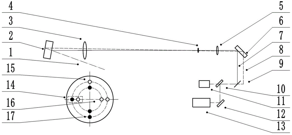
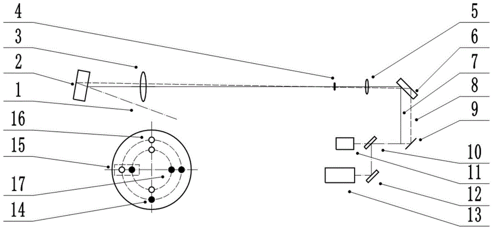
[0020] When the high-energy ultra-short pulse works according to the design value, the output state is: energy 1000J, pulse width 1-10ps adjustable, and the corresponding power is 10 +15 W. In the technical scheme proposed by the present invention, in order to realize the parameter diagnosis of the laser pulse under this condition, the high-energy ultrashort pulse becomes the measured pulse 1 after passing through a sampling mirror. The transmittance of the sampling mirror is T=1.5%. The measured pulse 1 first enters the first beam splitter 2, and then passes through the first lens 3, the gate aperture plate 4, and the second lens 5 to be incident on the dual channel second beam splitter 6. After the measured pulse 1 leaves the second beam splitter 6, two diagnostic pulses that are angularly parallel and spatially separated from each other are output, namely the high attenuation pulse 7 shown by the solid line and the low attenuation pulse 8 shown by the dashed line. After passing through the near-field translation mirror 9, these two diagnostic pulses are incident on the collimating beam splitter 10. After the collimating beam splitter 10, the transmission part enters the collimation monitoring unit 11, and the reflection part is introduced into the diagnostic device 13 by the diagnostic mirror 12.
[0021] The reflectivity of the front surface of the first beam splitter 2 is R=4%, and the reflectivity of the rear surface is R> 90%. The reflectivity of the front surface of the second beam splitter 6 is R=10%, and the reflectivity of the rear surface is R> 99%. Therefore, after the measured pulse passes through the high attenuation channel formed by the front surface of the first beam splitter 2 and the second beam splitter 6, the transmittance is T=4%×10%=4×10 -3 , The attenuation magnification of energy and power is 250 times; after passing through the low attenuation channel formed by the back surface of the first beam splitter 2 and the second beam splitter 6, the transmittance is T=(1-4%)×90%×( 1-4%)×(1-10%)×99%×(1-10%)=0.6651, the attenuation rate of energy and power is about 1.5 times.
[0022] The gate orifice plate 4 is provided with four sets of small hole combinations: the small orifice plate first combination 14, the small orifice plate second combination 15, the small orifice plate third combination 16, and the small orifice plate fourth combination 17. The first combination 14 of the small orifice plate is used to realize the conduction of high-attenuation pulses and the cut-off of low-attenuation pulses, and the second combination of small orifice plate 15 is used to realize the cut-off of high-attenuation pulses and conduction of low-attenuation pulses. The three combination 16 is used to realize the simultaneous conduction of the high attenuation pulse and the low attenuation pulse, and the fourth combination 17 of the small orifice plate is used to realize the simultaneous cutoff of the high attenuation pulse and the low attenuation pulse.
[0023] In order to ensure the normal operation of the diagnostic equipment 13, the working flow of the dual-channel optical beam reduction device is as follows:
[0024] 1) In the state of high attenuation channel, the gate orifice plate 4 is rotated to the position of the first combination of the orifice plate 14 to conduct figure 1 The high attenuation pulse 7 shown by the solid line in the middle is cut off the low attenuation pulse 8 shown by the dotted line; then, the near-field translation mirror 9 moves to the solid line position, and the collimation monitoring unit 11 is used to record and calculate the measured pulse drop at this time point.
[0025] 2) In the low-attenuation channel state, the gate orifice plate 4 is rotated to the position of the second combination 15 of the orifice plate, and it is turned on figure 2 The low-attenuation pulse 8 shown by the dotted line in the middle cuts off the high-attenuation pulse 7 shown by the solid line; then, the near-field translation mirror 9 moves to the dotted position, and the collimation monitoring unit 11 is used to record and calculate the measured pulse drop at this time point.
[0026] According to the design of the high-energy ultrashort pulse, the output energy is 1000J, the output energy is 7.24J in the debugging state, the pulse width is 1ps, and the sampling rate is 1.5%. The energy density and power density of the measured pulse in the dual-channel optical beam reduction device are calculated. The corresponding B points. The calculation results are shown in Table 1.
[0027] Table 1 Working characteristics of optical beam reduction device with attenuation function under high-energy ultrashort pulses
[0028]
[0029] Note: The diameter of the measured pulse is 32cm and the area is 804.25cm 2; The diameter of the beam after passing through the optical contraction lens is 4cm and the area is 12.57cm 2.
[0030] As can be seen from Table 1, due to the use of the optical beam reduction device with attenuation function, the high-energy ultrashort pulse can also effectively reduce the energy density and power density of the optical element and avoid the optical element under the output state of 1000J and 1ps. Damage, and reduce the influence of B integral on pulse width and time waveform. At the same time, during the debugging process of high-energy ultrashort pulse related equipment, the output energy is about 7.24J. After the optical beam reduction device with attenuation function, the energy density and power density are not much different from those in the 1000J output state. Performance testing and assessment of most related equipment.

PUM

no PUM

Description & Claims & Application Information

We can also present the details of the Description, Claims and Application information to help users get a comprehensive understanding of the technical details of the patent, such as background art, summary of invention, brief description of drawings, description of embodiments, and other original content. On the other hand, users can also determine the specific scope of protection of the technology through the list of claims; as well as understand the changes in the life cycle of the technology with the presentation of the patent timeline. Login to view more.
Why Eureka
Try Eureka