Surface element projection based triangular cross-sectional ray tube electromagnetic ray tracing algorithm

A tracking algorithm, electromagnetic ray technology, applied in the field of electromagnetic scattering simulation analysis, can solve problems such as time-consuming calculation

Active Publication Date: 2015-04-29
北京博奥瑞科技有限公司
View PDF2 Cites 18 Cited by
  • Summary
  • Abstract
  • Description
  • Claims
  • Application Information

AI Technical Summary

Problems solved by technology

Generally speaking, the shape of the target to be calculated is irregular, so many ray tubes do not intersect with the target, but it is still necessary to intersect with the surface element during the calculation process, which consumes a lot of calculation time

Method used


Image

  • Surface element projection based triangular cross-sectional ray tube electromagnetic ray tracing algorithm
  • Surface element projection based triangular cross-sectional ray tube electromagnetic ray tracing algorithm
  • Surface element projection based triangular cross-sectional ray tube electromagnetic ray tracing algorithm

Examples


Embodiment Construction

[0047] The present invention will be further described in detail below in conjunction with the accompanying drawings and embodiments.

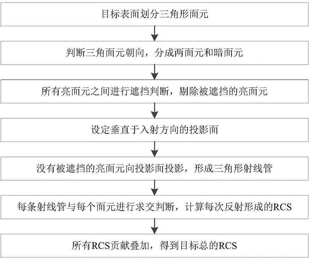
[0048] Such as figure 1 As shown, a kind of triangular section ray tube electromagnetic ray tracing algorithm based on panel projection of the present invention comprises the following steps:

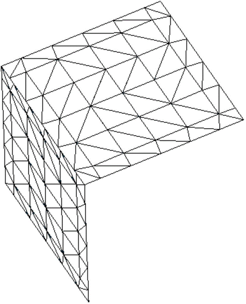
[0049] Step 1: Divide the target surface into triangular surface elements: Divide the target surface to be calculated into many triangular surface elements for approximation. The advantage of using triangular surface elements is that the mesh division is more flexible, and any three vertices are on the same plane, which is convenient for subsequent Integral calculation of physical optics.

[0050] Step 2: Determine the orientation of the triangular bins, and divide them into bright bins and dark bins: judge their orientation according to the normal direction of the bins, the bins whose normal direction faces the direction of the incident electromagnet...


PUM


Abstract

Disclosed is a surface element projection based triangular cross-sectional ray tube electromagnetic ray tracing algorithm. The surface element projection based triangular cross-sectional ray tube electromagnetic ray tracing algorithm comprises the steps of, firstly, dividing a target surface into triangular surface elements for approximation; secondly, determining the orientation of the surface elements, and defining the surface elements facing towards the normal direction as light surface elements and those facing towards the back direction as dark surface elements; thirdly, performing shadowing judgment on the light surface elements to eliminate shadowed light surface elements; fourthly, setting a plane, which passes through an original point and is perpendicular to an incident direction, as a projection surface; fifthly, projecting the light surface elements onto the projection surface, and taking projected triangles as the cross section to form a ray tube in the incident direction of electromagnetic rays; sixthly, determining the intersection situations between the ray tube and the surface elements of the target surface to compute reflecting rays ad further to compute the RCS (radar cross section) formed during every reflection, wherein a first reflecting surface is the light surface element forming the ray tube; seventhly, superpositioning the RCSs formed by reflection of the reflecting tube to obtain a total RCS. By correlating the ray tube with the target surface elements, the surface element projection based triangular cross-sectional ray tube electromagnetic ray tracing algorithm eliminates errors generated by interaction between traditional rectangular ray tubes and triangular surface elements.

Description

1. Technical field [0001] The invention discloses an electromagnetic ray tracing algorithm for a triangular-section ray tube based on panel projection, belonging to the field of electromagnetic scattering simulation analysis. 2. Background technology [0002] The ray tracing method is an electromagnetic simulation method for calculating the electromagnetic scattering in the high-frequency region of the target. The main method is to divide the incident wave into many ray tubes, track the reflection of each ray tube on the target surface, and the reflection direction of the ray tube on the target surface , amplitude and phase are calculated based on geometric optics. Every time the ray tube irradiates the target surface, electromagnetic scattering will be formed, and the electromagnetic scattering formed by all the ray tubes on the target surface will be superimposed to obtain the total electromagnetic scattering, and then the radar cross section (RCS) of the target can be obt...

Claims


Application Information

Patent Timeline
Patent Type & Authority Applications(China)
IPC IPC(8): G06F19/00
Inventor 姬金祖马云鹏黄沛霖孙康文
Owner 北京博奥瑞科技有限公司
Why Eureka
Try Eureka