Check patentability & draft patents in minutes with Patsnap Eureka AI!

Optical remote sensing image decomposition algorithm

An optical remote sensing image and image technology, applied in the field of optical remote sensing image decomposition algorithms, can solve the problems of time-consuming, difficult to popularize, lack of theoretical basis, etc., and achieve the effect of improving the effect.

Inactive Publication Date: 2015-04-29
BEIJING RES INST OF URANIUM GEOLOGY
View PDF4 Cites 3 Cited by
  • Summary
  • Abstract
  • Description
  • Claims
  • Application Information

AI Technical Summary

Benefits of technology

This patented technology allows us to use operations like multiplication or addition to manipulate images captured through different types of cameras. It decomposes them based upon their characteristics such as size, shape, texture etc., which makes it easier than previous methods due to its ability to calculate both numerical values and spectral properties simultaneously with each other. By doing this we aimed at improving image resolution and identification capabilities while reducing errors caused by factors like uneven ground surfaces.

Problems solved by technology

Technics: Remote Sensing (RS) technology can be useful for studying materials that are distributed over large areas or surfaces due to their geometry. Current methods involve analyzing high resolution imagery data from multiple small sections taken by satellites orbit around Earth. These techniques have limitations such as requiring laborious experimental comparisons between observed and simulated samples which may result in errors when determining decompositions based solely upon physical properties like heights or width dimensions alone.

Method used


Image

  • Optical remote sensing image decomposition algorithm
  • Optical remote sensing image decomposition algorithm

Examples


Embodiment Construction

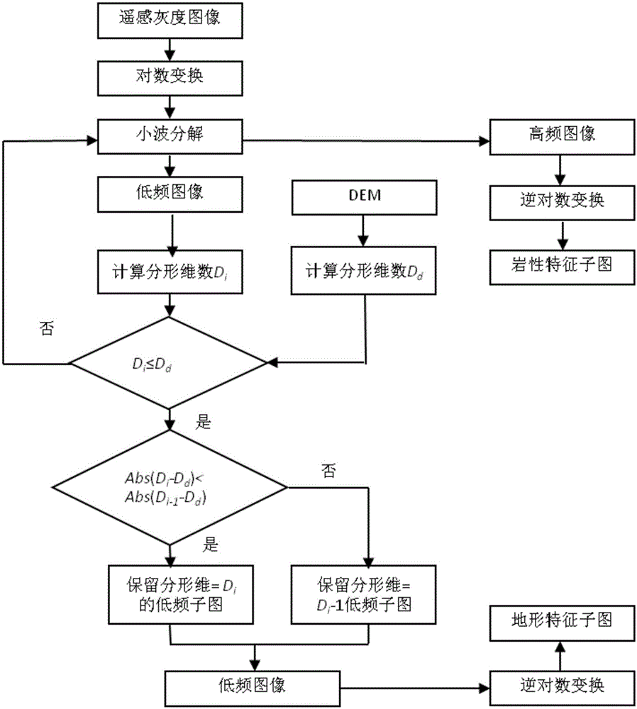
[0030] An optical remote sensing image decomposition algorithm, comprising the following steps:

[0031] Step 1: Data reading

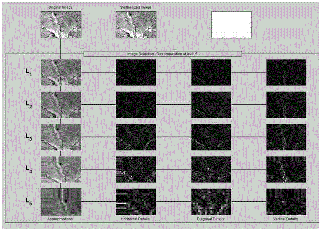
[0032] Read the stored original image data, and the read image is the gray value, that is, the data obtained in this step is a three-dimensional array, in which two dimensions are the horizontal and vertical coordinates of the image, and the third dimension is the gray value corresponding to the coordinates. The result obtained in this step is represented by (x, y, F(x, y)), where x, y are the horizontal and vertical coordinates of the image, and F(x, y) is the gray value of the point (x, y).

[0033] Step 2: Logarithmic transformation

[0034] Take the logarithm of F(x,y), that is, f(x,y)=lg(F(x,y)).

[0035] In this step, the two factors that affect the remote sensing image - surface objects and terrain, are converted from multiplicative operations to additive operations.

[0036] The result obtained in this step is represented by (x, y, f(x, y))...


PUM


Abstract

The invention belongs to the field of remote sensing image processing and particularly relates to an optical remote sensing image decomposition algorithm. The optical remote sensing image decomposition algorithm comprises the following steps: step 1, reading the stored original image data; step 2, performing logarithmic transformation; taking logarithm of F(x, y), and F (x, y)=1g(F(x, y)); step 3, performing wavelet decomposition; carrying out discrete wavelet transformation, wherein the wavelet basis is haar wavelet; step 4, performing inverse transformation; using zero to substitute {Hp, t} for wavelet inverse transformation with low-frequency subgraphs Lt to obtain low-frequency image Li in the image f spatial domain; step 5, conducting fractal computation; step 6, performing cyclic judgment; if Di is less than or equal to Dd, actuating step 7, otherwise, adding 1 to i, and then actuating the step 3 (wavelet decomposition); step 7, performing optimal dimension judgment; step 8, realizing image generation. The optical remote sensing image decomposition algorithm has the effect of solving the problem that the traditional image decomposition algorithm cannot accurately judge the optimal decomposition dimension.

Description


Claims


Application Information

Patent Timeline
Owner BEIJING RES INST OF URANIUM GEOLOGY
Features
  • R&D
  • Intellectual Property
  • Life Sciences
  • Materials
  • Tech Scout
  • Unparalleled Data Quality
  • Higher Quality Content
  • 60% Fewer Hallucinations
Learn More