
Bernoulli principle experiment instrument

A technology based on Bernoulli's principle and experimental instrument, which can be used in instruments, educational appliances, teaching models, etc., and can solve problems such as outdated experimental plans.

Inactive Publication Date: 2015-04-29
曾颖
View PDF0 Cites 3 Cited by
  • Summary
  • Abstract
  • Description
  • Claims
  • Application Information

AI Technical Summary

Problems solved by technology

[0004] Most of the existing Bernoulli experiments that study the relationship between fluid pressure and flow velocity are outdated, and lack an experimental method that is innovative and has improved effects

Method used


Image

  • Bernoulli principle experiment instrument

Examples


Embodiment Construction

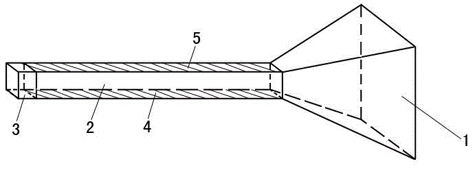
[0013] Such as figure 1 As shown, it includes a strip-shaped air passage, which is surrounded by two opposite support plates 2, and two opposite first rubber films 4 and second rubber films 5, and the support plate 2 is formed by Made of transparent material, the first rubber film 4 and the second rubber film 5 are all stretched, straight and sealed and pasted on the support plate 2. One end of the air passage is fixed with a trumpet-shaped air inlet 1, and the other end of the air passage An air outlet 3 is fixed.


PUM


Abstract

A Bernoulli principle experiment instrument is characterized by comprising a long strip-shaped air duct, wherein the air duct is jointly defined by two oppositely arranged support plates and two oppositely arranged rubber membranes; each support plate is made of a transparent material; the rubber membranes are flatly sealed and glued on the support plates; a horn-shaped air inlet is fixed in one end of the air duct; an air outlet is fixed in the other end of the air duct. The Bernoulli principle experiment instrument has the benefits as follows: an electric hair drier faces the horn-shaped air inlet to blow air, airflow rapidly flows through in the air duct, the pressure intensity is reduced, the rubber membranes are sunken inwards under the action of external pressure intensity, and the phenomenon is remarkable. The support plates are made of the transparent material, so that the observation is facilitated. The Bernoulli principle experiment instrument has the advantages of convenience in operation and repeatability.

Description

[0001] technical field [0002] The invention relates to a physics teaching appliance, in particular to a Bernoulli principle experiment instrument. [0003] Background technique [0004] Most of the existing Bernoulli experiments for studying the relationship between fluid pressure and flow velocity are outdated, and there is a lack of an experimental method with new ideas and improved effects. [0005] Contents of the invention [0006] The purpose of this invention is: to solve the above problems, a kind of Bernoulli principle experimental instrument is provided. [0007] The technical solution adopted by the present invention is: a Bernoulli principle experiment instrument, characterized in that it comprises a strip-shaped air channel, and the air channel is composed of two oppositely arranged support plates and two oppositely arranged The rubber film is surrounded together, the support plate is made of transparent material, and the rubber film is pasted on the sup...

Claims


Application Information

Patent Timeline
Patent Type & Authority Applications(China)
IPC IPC(8): G09B23/12
CPCG09B23/12
Inventor 曾颖
Owner 曾颖
Learn More