Current transformer mounting plate convenient for mounting
A technology for current transformers and mounting boards, which is applied in the field of mounting boards to improve assembly efficiency, solve installation inconvenience, and facilitate detection
- Summary
- Abstract
- Description
- Claims
- Application Information
AI Technical Summary
Problems solved by technology
Method used
Image

Examples
Embodiment Construction
[0015] The technical solutions of the present invention will be further described below in conjunction with the accompanying drawings and through specific implementation methods.
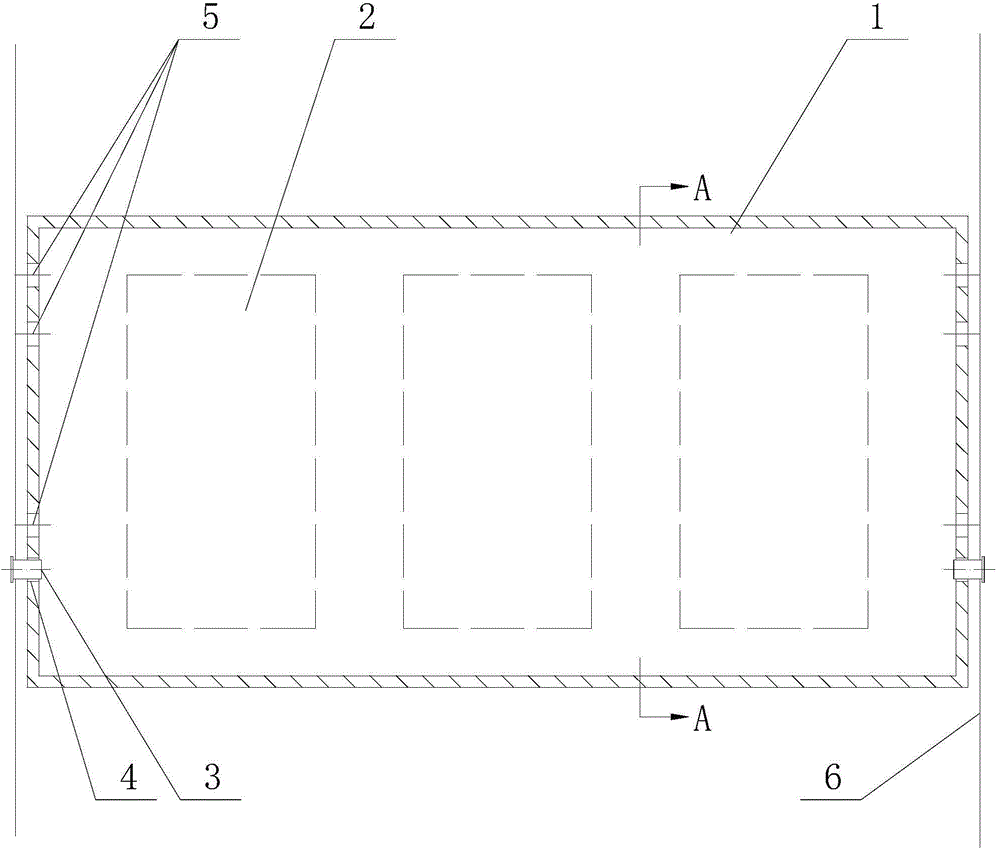
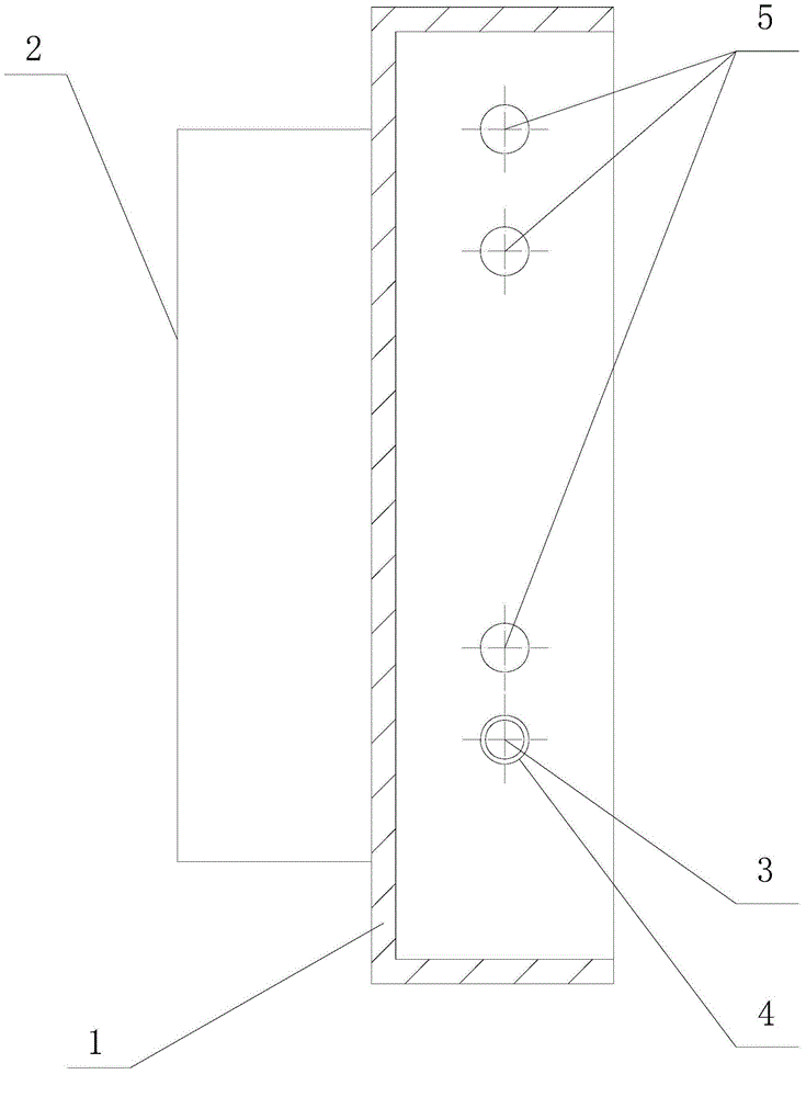
[0016] see figure 1 , figure 2 as shown, figure 1 It is a schematic structural diagram of a current transformer mounting plate for easy installation provided in Embodiment 1 of the present invention, figure 2 yes figure 1 A-A direction view.
[0017] In this embodiment, a current transformer mounting plate that is easy to install includes a cabinet body 6 and a mounting plate 1. Several current transformers 2 are installed on the inside of the mounting plate 1, and the mounting plate 1 is fixed to the cabinet. Inside the body 6, a positioning bolt 3 and a through hole 4 are provided between the installation board 1 and the cabinet body 6 to facilitate turning over the installation board 1 . The mounting plate 1 can be processed from a plate, and its four sides are all folded, and a positionin...
PUM
 Abstract
Description
Claims
Application Information
 - R&D
- Intellectual Property
- Life Sciences
- Materials
- Tech Scout
- Unparalleled Data Quality
- Higher Quality Content
- 60% Fewer Hallucinations
Browse by: Latest US Patents, China's latest patents, Technical Efficacy Thesaurus, Application Domain, Technology Topic, Popular Technical Reports.
© 2025 PatSnap. All rights reserved.Legal|Privacy policy|Modern Slavery Act Transparency Statement|Sitemap|About US| Contact US: help@patsnap.com