Motor

A terminal pin and wire winding technology is applied in the field of motors and in the field of connecting winding wires to terminal pins in motors, which can solve the problems of hanging on other components, floating, damage, etc., and achieve the effect of suppressing the floating of the winding wire.

Inactive Publication Date: 2015-04-29
SANKYO SEIKI MFG CO LTD
View PDF7 Cites 7 Cited by
  • Summary
  • Abstract
  • Description
  • Claims
  • Application Information

AI Technical Summary

Problems solved by technology

However, when the coiled wire is pulled along the surface of the terminal block, if the coiled wire has slack, the coiled wire will float from the surface of the terminal block
In such a state, the floating winding wire may be caught on other parts, causing the winding wire to break or be damaged.

Method used


Image

  • Motor
  • Motor
  • Motor

Examples


Embodiment Construction

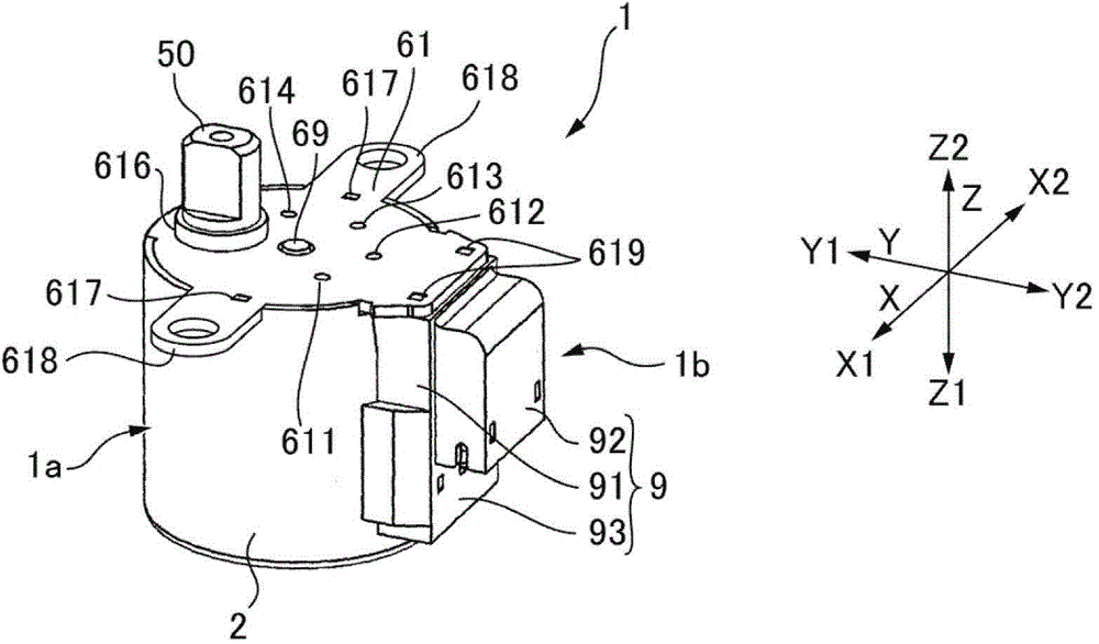
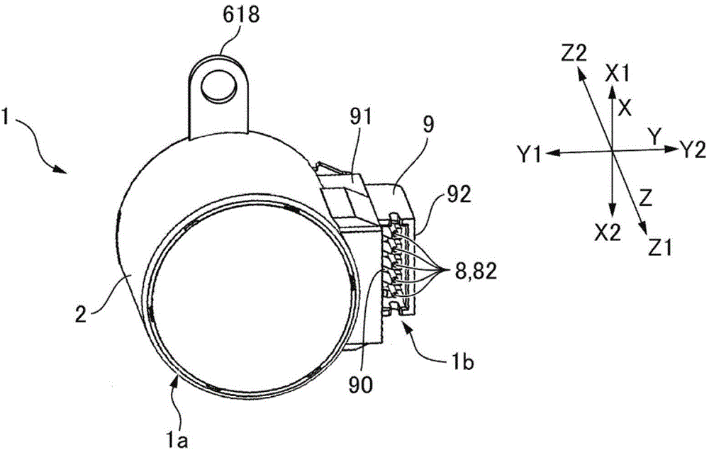
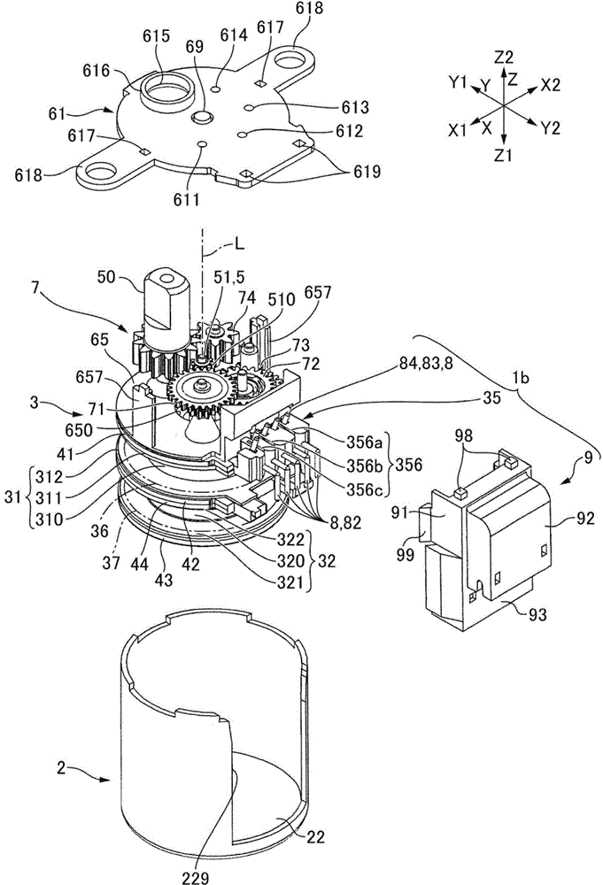
[0107] Hereinafter, a motor to which the present invention is applied will be described with reference to the drawings. In addition, in the following description, the three mutually orthogonal directions are referred to as the X-axis direction, the Y-axis direction, and the Z-axis direction, and the motor axis direction is referred to as the Z-axis direction. Also, let one side in the X-axis direction be X1 side, let the other side in the X-axis direction be X2 side, let one side in the Y-axis direction be Y1 side, and let the other side in the Y-axis direction be Y2 One side in the Z-axis direction will be described as the Z1 side, and the other side in the Z-axis direction will be described as the Z2 side. The side where the output shaft of the motor protrudes is the Z2 side.

[0108] 1( a ), FIG. 1( b ) are external views of a motor according to an embodiment of the present invention, and FIG. 1( a ) is a perspective view of the motor viewed from the output side (Z2 side) ...


PUM


Abstract

The utility model provides a motor. The motor draws and winds coiled lines of coils to a terminal block and connects the coiled lines to terminal pins so as to restrain loosed coiled lines from floating up from the terminal block. The terminal block is formed on the motor, and the terminal pins are kept on the terminal block. In a first face of the terminal block, facing a motor axis direction, and a second face, facing a radial-direction outer side, winding line arrangement grooves are formed. First groove parts of the winding line arrangement grooves extend to base parts of winding line binding parts of the terminal pins on the first face. During observation in a direction which is orthogonal to the extending direction of the first groove parts, each first groove part extends to a position which coincides with at least a part of the base part of a corresponding winding line binding part. Because the tail ends of first and second coils and the tail end of a public line are drawn and wound to the base parts of the winding line binding parts in a state of being accommodated in the coil arrangement grooves, even in a loose state, changing into a state of floating from the surface of the terminal block can also be restrained.

Description

technical field [0001] The present invention relates to a motor and a method of connecting a winding wire to a terminal pin in the motor, the motor includes a terminal block holding the terminal pin, and connects the winding wire to the terminal pin to supply power to a coil. Background technique [0002] Conventionally, a stepping motor has been proposed in which a terminal pin to which a wound wire constituting a coil is connected is held on a terminal block, and a connector is fitted to the terminal pin protruding from the terminal block (see Patent Document 1). In the stepping motor of Patent Document 1, a terminal block (terminal mounting member) is integrally formed on a flange portion of a bobbin on which a coiled wire is wound. Five terminal pins are mounted in a row on the terminal block. Each terminal pin has a substantially vertically bent shape, and one end of each terminal pin protrudes outward in the radial direction of the bobbin from the terminal base, and t...

Claims


Application Information

Patent Timeline
Patent Type & Authority Applications(China)
IPC IPC(8): H02K3/50H02K5/22
Inventor 伊藤敏朗
Owner SANKYO SEIKI MFG CO LTD
Why Eureka
Try Eureka