Motor and disk driving device

A technology of rotating drive and mounting board, applied in electromechanical devices, electric components, connection with control/drive circuits, etc., can solve problems such as warpage of printed circuit boards

Inactive Publication Date: 2015-01-21
NIDEC CORP
View PDF5 Cites 0 Cited by
  • Summary
  • Abstract
  • Description
  • Claims
  • Application Information

AI Technical Summary

Problems solved by technology

[0007] In addition, in the case where the printed circuit board has a locally constricted shape, warping of the printed circuit board is also likely to occur.

Method used


Image

  • Motor and disk driving device
  • Motor and disk driving device
  • Motor and disk driving device

Examples


Embodiment Construction

[0055] Hereinafter, exemplary embodiments of the present invention will be described with reference to the drawings. In addition, below, the direction along the central axis of the motor is referred to as the vertical direction, and the circuit board side is referred to as the upper side with respect to the mounting board, and the shape and positional relationship of each part will be described.

[0056] However, this is merely a method of defining the up and down directions for convenience of description. This definition does not limit the installation posture when the motor and disk drive device of the present invention are mounted on an actual device.

[0057]

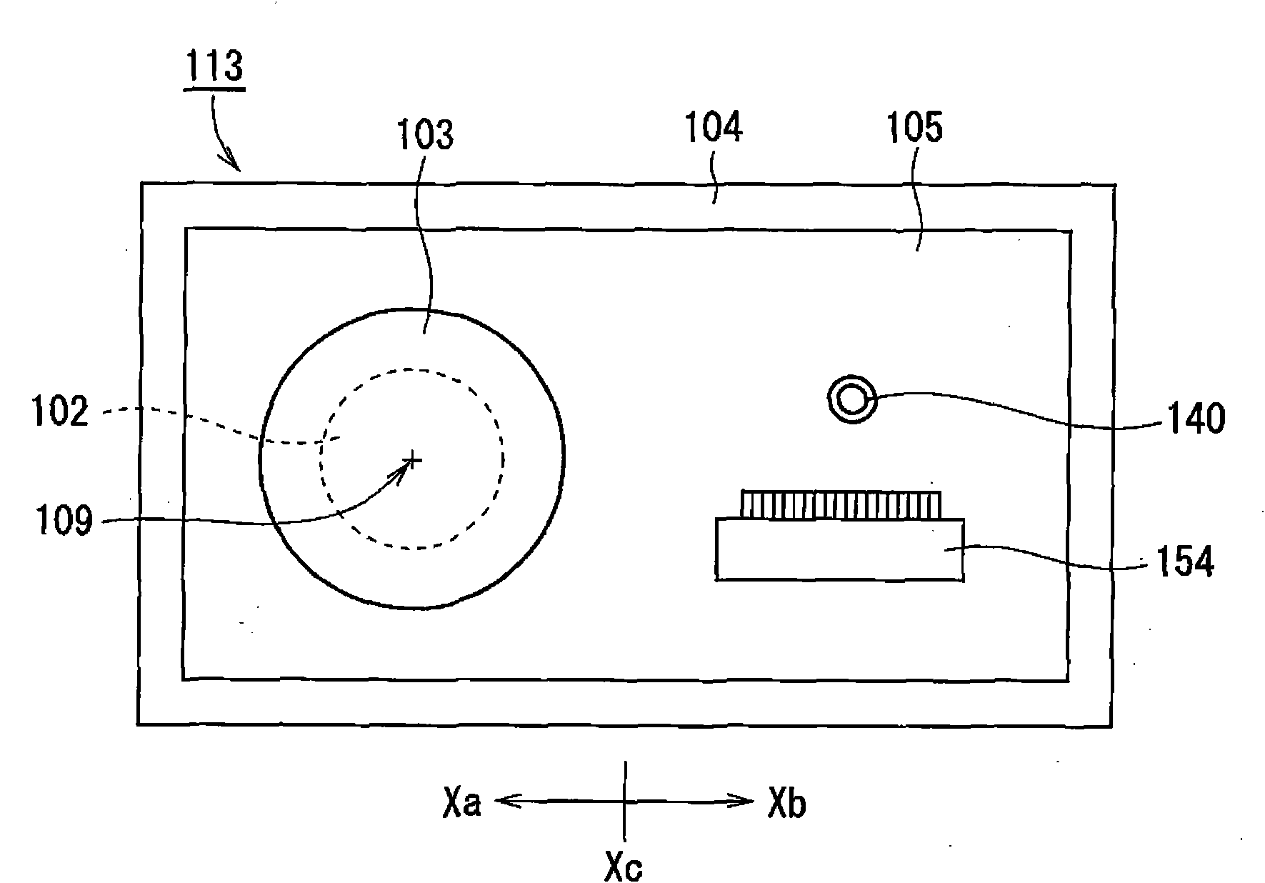
[0058] figure 1 It is a plan view of the motor 113 of 1st Embodiment of this invention. Such as figure 1 As shown, the motor 113 includes a stationary part 102 , a rotating part 103 , a mounting plate 104 , and a circuit board 105 .

[0059] The stationary part 102 is fixed on the mounting plate 104 . The rot...


PUM


Abstract

The present invention provides a motor which comprises the following components: a stationary part, a rotating part which is supported by the stationary part at a state of rotating round a central shaft that extends vertically, a mounting plate for fixing stationary part, and a circuit substrate which is configured at an upper side of the mounting plate and is provided with an electronic circuit that is used for rotatably driving the rotating part relatively to the stationary part. The stationary part is provided at one side of a central position in a length direction of the circuit substrate. The circuit substrate is provided with a connector which is provided at the other side of the central position in the length direction. The mounting plate is provided with a riveting partwhich abuts against an upper surface of the circuit substrate for fixing the circuit substrate. At least one riveting part is configured at a position of the other side of one end at one side of the connector. The circuit substrate is mechanically fixed on the mounting plate at the periphery of the connector where warpage easily generates in the circuit substrate. Therefore, the circuit substrate can be fixed on the mounting plate without pushing the circuit substrate to the upper surface of the mounting plate.

Description

technical field [0001] The invention relates to a motor and a disk drive device. Background technique [0002] A brushless motor for rotating a disk is mounted on a disk drive device such as an optical disk drive. The structure of the conventional brushless motor is described in Unexamined-Japanese-Patent No. 2002-262540, for example. The brushless motor described in this publication has a mounting base for mounting the motor, and a printed circuit board on which at least part of a circuit for driving and controlling the motor is mounted. [0003] Patent Document 1: Japanese Laid-Open Publication No. 2002-262540 [0004] In the brushless motor described in Japanese Laid-Open Publication No. 2002-262540, the printed circuit board is glued and fixed on the mounting base with double-sided adhesive. However, when various electronic components are soldered to a printed circuit board, the printed circuit board may warp due to heat. When fixing a warped printed circuit board to...

Claims


Application Information

Patent Timeline
Patent Type & Authority Patents(China)
IPC IPC(8): H02K11/00G11B19/20H02K11/33
Inventor 日高秀彦林重雄中村昌典
Owner NIDEC CORP
Why Eureka
Try Eureka