Punching die of die

A punching die and mold technology, applied in the direction of manufacturing tools, metal processing equipment, stripping devices, etc., can solve problems such as poor discharge of punching waste, difficulty in making dies, and concerns about the durability of dies

Pending Publication Date: 2021-09-14
株式会社HARZ
View PDF12 Cites 0 Cited by
  • Summary
  • Abstract
  • Description
  • Claims
  • Application Information

AI Technical Summary

Problems solved by technology

However, if the protrusion is formed longitudinally along the punching direction, the friction generated before the punch reaches the lowest point is large, and the durability of the die is concerned.
Furthermore, in the case where the protrusion is integrally formed, it becomes difficult to manufacture the die itself.
In addition, if a plate-shaped protrusion is formed on the entire circumference of the inner peripheral surface of the punching hole, even if the occurrence of scrap floating up is suppressed, there is a concern that the degree of catching is large and the punching scrap is stuck in the die and there is a possibility of poor discharge. Happening

Method used


Image

  • Punching die of die
  • Punching die of die
  • Punching die of die

Examples


no. 1 approach

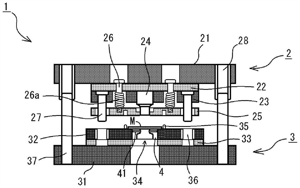
[0040] figure 1 The whole of the mold 1 according to this embodiment is shown. In actual product processing, there are cases where multiple sets of punches and dies are used, or other processing such as deep drawing is performed simultaneously with one die, but in order to facilitate understanding of the invention, in figure 1 exemplifies a typical die 1 for punching (piercing) with a set of punches and dies.

[0041] Such as figure 1 As shown, the mold 1 is composed of a set of upper mold 2 and lower mold 3 . The upper die 2 is attached to a slide of the press machine by, for example, a flange-type shank not shown. On the other hand, the lower die 3 is mounted on a backing plate of the press machine. In the upper die 2 , a punch holder 21 is arranged at the uppermost position, and a backing plate 22 and a punch plate 23 are arranged on the lower surface side thereof. At the center of the upper die 2 , a cylindrical punch 24 for circularly punching the material M to be pr...

no. 2 approach

[0053] Next, while referring to Figure 4 The die 34 according to the second embodiment will be described. In addition, the die 34 according to the second embodiment is the same as that of the first embodiment except that the configuration of the resistance member 41 is different. Therefore, the same reference numerals are assigned to the same configurations as those of the first embodiment, and detailed description thereof will be omitted.

[0054] In the second embodiment, as Figure 4 As shown, instead of the rod-shaped member, the plunger 5 is used to constitute the elongated resistance member 41 . The plunger 5 includes a housing 51 as a main body, a front end portion 52 provided in an opening on one end side of the housing 51 to be able to move forward and backward, and an elastic member 53 biasing the front end portion 52 . The casing 51 is a substantially cylindrical member that is open at one end and has a bottom at the other end, and has a helical thread on its ou...


PUM


Abstract

The invention provides a novel punching die of a die and capable of suppressing waste floating generated during punching. The punching die is composed of a punching die body (4) and slender resistance members (41); a punched hole (42) provided with a gap (C) relative to the peripheral surface of a punch (24) is formed in the punching direction of a machined material (M); and the slender resistance members (41) are nested inside the punching die body in the direction intersecting with the punching direction at the position lower than the upper surface of the punched hole, and the front ends of the slender resistance members (41) protrude to the positions where the slender resistance members (41) make contact with a part of punched waste (S) when the punch advances and retreats in the punched hole.

Description

technical field [0001] The present invention relates to a punching die of a mold, and in particular to a technique for suppressing the floating of scrap generated when punching is performed. Background technique [0002] As one of the methods of processing a workpiece such as a metal plate into a desired shape, there is punching. Punching is performed by, for example, manufacturing a set of upper and lower molds that are assembled with a punch (Punch) and a die (Die) corresponding to the shape to be punched, such as a circle or a rectangle, and sandwiching the material to be processed with the mold installed in the punching machine. Press to carry out. [0003] In general, the die disposed on the lower die is provided with a discharge hole having an inner periphery wider than the punch hole below the punch hole. Punching waste generated when the punch advances and retreats through the punching hole falls from the die through the discharge hole and is discharged. However, ...

Claims


Application Information

Patent Timeline
Patent Type & Authority Applications(China)
IPC IPC(8): B21D28/14B21D45/08
CPCB21D28/14B21D45/08
Inventor 近藤大辅
Owner 株式会社HARZ
Why Eureka
Try Eureka