Air-jet vortex spinning process and product for making antibacterial yarn
A vortex spinning and yarn technology, which is applied to textiles, papermaking, yarn, spinning machines, etc., can solve the problems of difficult production and difficult production, and achieve the effects of easy realization, strong antibacterial effect, and easy realization.
- Summary
- Abstract
- Description
- Claims
- Application Information
AI Technical Summary
Problems solved by technology
Method used
Image
Examples
Embodiment 1
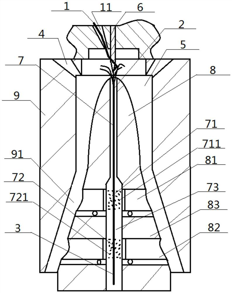
[0052] see figure 1 — image 3 , an air-jet vortex spinning process for making antibacterial yarns, the air-jet vortex spinning process includes the following steps: first inject pressurized gas into the vortex chamber 5 from the air injection hole 4 to form a rotating air flow, and then input it into the fiber channel 11 The fiber bundle 1, subsequently, the fiber bundle 1 enters the vortex chamber 5 under the action of the guide needle 6, wherein, a part of the fiber bundle 1 enters the yarn guiding channel 7 to become a core fiber, while the remaining part of the fiber bundle 1 follows the airflow Turn around to wrap the core fiber to form the primary yarn 2, and output it from the yarn introduction channel 7 outwards, while outputting, the tube spindle gap 91 sandwiched between the vortex tube 9 and the hollow spindle 8 is discharged outwards gas; in the process of the primary yarn 2 being exported through the yarn-drawing passage 7, the primary yarn 2 successively passes...
Embodiment 2
[0055] Basic content is the same as embodiment 1, the difference is:
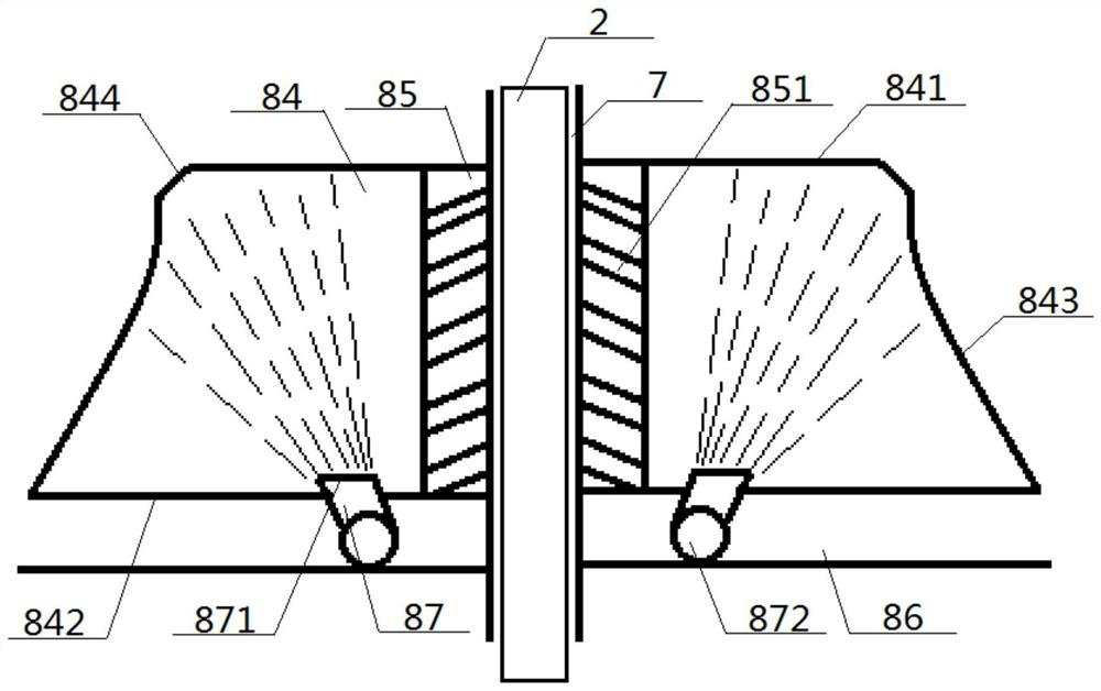
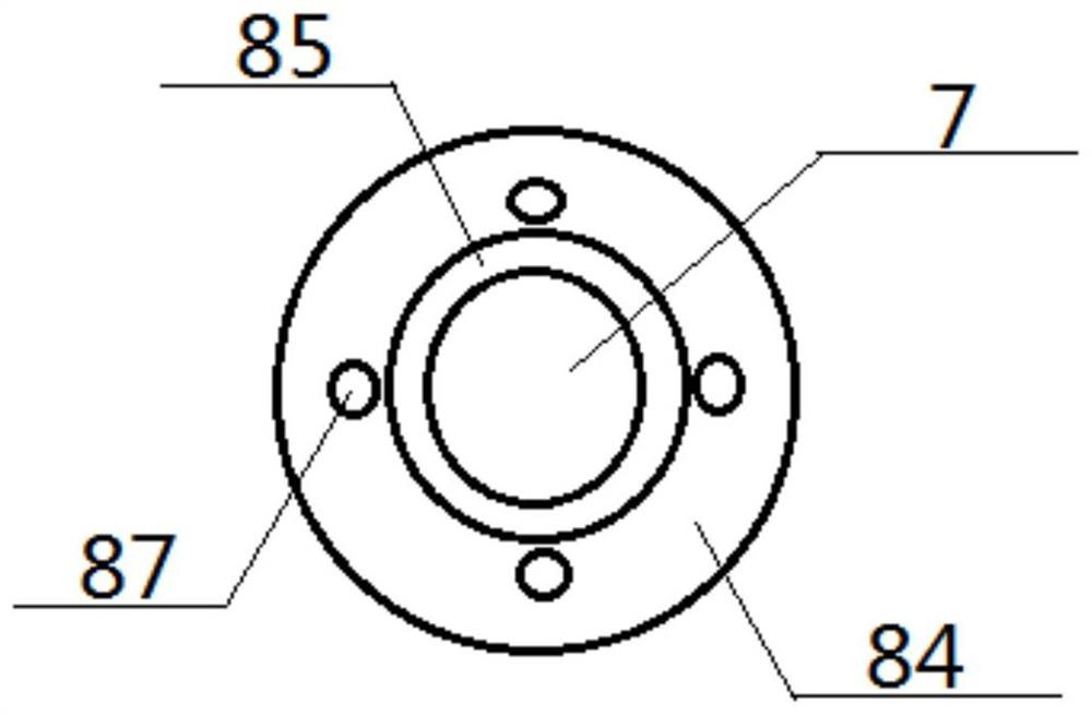
[0056] The inner wall of the hollow spindle 8 is provided with a cation coating section 81 and an anion coating section 82, a non-coating section 83 between the cation coating section 81 and anion coating section 82, the cation coating section 81, the anion coating section 82, and the anion coating section 81. The coating sections 82 are all arranged around the yarn guiding channel 7, the cationic coating section 81 transports the cationic water mist 711 into the cationic coating area 71, and the anionic coating section 82 transports the anionic water mist 721 into the anion coating area 72 . Preferably, the cationic coating section 81 and the anionic coating section 82 have the same structure, and both include a mist-generating ring 84, a mist-discharging ring 85 and a nozzle ring 86, and the nozzle ring 86, mist-generating ring 84, and mist-discharging ring 85 all surround the guide ring. The yarn channe...
Embodiment 3
[0058] Basic content is the same as embodiment 2, the difference is:
[0059] The mist outlet pipe 851 is arranged obliquely, and the end of the mist outlet pipe 851 that communicates with the yarn guiding channel 7 is higher than the end of the mist outlet pipe 851 that communicates with the mist generating ring 84 . The top of the liquid nozzle 87 is a mouth 871 , and the bottom of the liquid nozzle 87 communicates with external equipment through a liquid inlet 872 .
PUM
 Abstract
Description
Claims
Application Information
 - R&D
- Intellectual Property
- Life Sciences
- Materials
- Tech Scout
- Unparalleled Data Quality
- Higher Quality Content
- 60% Fewer Hallucinations
Browse by: Latest US Patents, China's latest patents, Technical Efficacy Thesaurus, Application Domain, Technology Topic, Popular Technical Reports.
© 2025 PatSnap. All rights reserved.Legal|Privacy policy|Modern Slavery Act Transparency Statement|Sitemap|About US| Contact US: help@patsnap.com


