A device and method for improving the utilization rate of permanent magnet motor starting cage bars
A technology of permanent magnet motor and utilization rate, which is applied in the direction of electromechanical devices, synchronous machines, electrical components, etc., can solve the problems of reducing the utilization rate of starter cages, achieve the goals of shortening start-up time, low manufacturing cost, and increasing the speed-up of magnetic field weakening effect of ability
- Summary
- Abstract
- Description
- Claims
- Application Information
AI Technical Summary
Problems solved by technology
Method used
Image
Examples
Embodiment 1
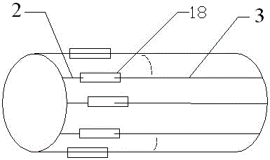
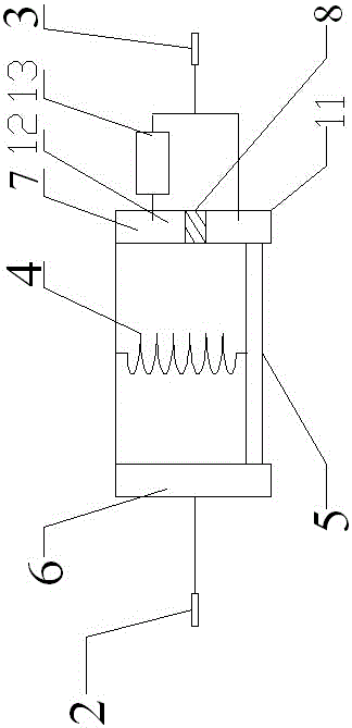
[0027] like image 3 As shown, the right slide rail 7 is provided with a first conductive block 11 and a second conductive block 12 from bottom to top, the first conductive block 11 is connected to the second half section 3 of the starting cage, and the second conductive block 12 passes through the first thyristor 13. It is connected to the second half section 3 of the starting cage, and the second conductive block 12 is connected to the S pole of the first thyristor 13. When the motor reaches a medium speed after starting, the centrifugal force on the conductive slide 5 is greater than the elastic force of the spring 4, and the two ends of the conductive slide 5 Move upward in the left slide rail 6 and the right slide rail 7 respectively, the conductive slide 5 is connected with the second conductive block 12, and the first thyristor 13 limits the direction of the current in the starting cage, so that the direction of the eddy current generated by the starting cage is the same...
Embodiment 2
[0029] like Figure 4 As shown, referring to Embodiment 1, the right slide rail 7 is provided with a first conductive block 11 and a second conductive block 12 from bottom to top. The conductive block 12 is connected to the second half section 3 of the starting cage through the first thyristor 13, and the second conductive block 12 is connected to the S pole of the first thyristor 13. When the motor is ready to start or rotate at a low speed, the conductive slide 5 is connected to the first conductive block 11. Connected, resistor 14 reduces the current in the starting cage, thereby allowing the motor to obtain more starting torque.
Embodiment 3
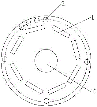
[0031] like Figure 5 As shown, referring to Embodiment 2, the right slide rail 7 is provided with a first conductive block 11, a second conductive block 12 and a third conductive block 15 from bottom to top. Section 3 is connected, the second conductive block 12 is connected to the second half section 3 of the starting cage through the first thyristor 13, the second conducting block 12 is connected to the S pole of the first thyristor 13, and the third conducting block 15 is directly connected to the second half of the starting cage. Section 3 is connected. When the motor runs at a high speed, the conductive sliding plate 5 moves upward under the action of centrifugal force and is connected to the third conductive block 15. Due to the poor excitation performance of the ferrite permanent magnet rotor 1, the motor realizes a weak magnetic field increase. fast effect.
PUM
 Abstract
Description
Claims
Application Information
 - R&D
- Intellectual Property
- Life Sciences
- Materials
- Tech Scout
- Unparalleled Data Quality
- Higher Quality Content
- 60% Fewer Hallucinations
Browse by: Latest US Patents, China's latest patents, Technical Efficacy Thesaurus, Application Domain, Technology Topic, Popular Technical Reports.
© 2025 PatSnap. All rights reserved.Legal|Privacy policy|Modern Slavery Act Transparency Statement|Sitemap|About US| Contact US: help@patsnap.com


