Device and method for increasing utilization rate of starting cage bar of permanent magnet motor

A technology of permanent magnet motor and utilization rate, which is applied in electromechanical devices, synchronous machines, electrical components, etc., can solve the problems of reducing the utilization rate of starting cages, and achieve the effects of shortening start-up time, simple structure and convenient use

Inactive Publication Date: 2015-04-29
ZHENGZHOU UNIVERSITY OF LIGHT INDUSTRY
View PDF4 Cites 0 Cited by
  • Summary
  • Abstract
  • Description
  • Claims
  • Application Information

AI Technical Summary

Problems solved by technology

[0004] However, the starter cage only works when the motor is started, and the cage does not play a role when the motor is running stably, which reduces the utilization rate of the starter cage

Method used


Image

  • Device and method for increasing utilization rate of starting cage bar of permanent magnet motor
  • Device and method for increasing utilization rate of starting cage bar of permanent magnet motor
  • Device and method for increasing utilization rate of starting cage bar of permanent magnet motor

Examples


Embodiment 1

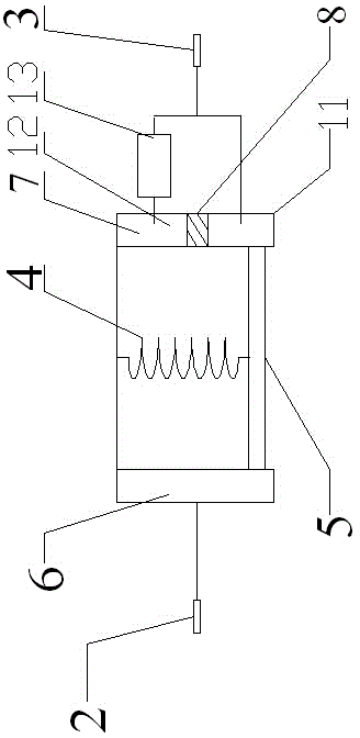
[0027] Such as image 3 As shown, the right slide rail 7 is provided with a first conductive block 11 and a second conductive block 12 from bottom to top, the first conductive block 11 is connected to the second half section 3 of the starting cage, and the second conductive block 12 is connected to It is connected with the second half section 3 of the starting cage, and the second conductive block 12 is connected with the S pole of the first thyristor 13. When the motor reaches a medium speed after starting, the centrifugal force received by the conductive slide plate 5 is greater than the elastic force of the spring 4, and the two ends of the conductive slide plate 5 Respectively move upwards in the left slide rail 6 and the right slide rail 7, the conductive slider 5 is connected with the second conductive block 12, and the first thyristor 13 limits the direction of the current in the starting cage so that the direction of the eddy current generated by the starting cage ...

Embodiment 2

[0029] Such as Figure 4 As shown, with reference to Embodiment 1, the right slide rail 7 is provided with a first conductive block 11 and a second conductive block 12 from bottom to top, the first conductive block 11 is connected with the second half of the starting cage 3 through a resistor 14, and the second The conductive block 12 is connected to the second half of the starting cage 3 through the first thyristor 13, and the second conductive block 12 is connected to the S pole of the first thyristor 13. When the motor is ready to start or rotate at a low speed, the conductive slide 5 and the first conductive block 11 Connected, the resistor 14 reduces the current in the starter cage, so that the motor can get a larger starting torque.

Embodiment 3

[0031] Such as Figure 5 As shown, referring to Embodiment 2, the right slide rail 7 is provided with a first conductive block 11, a second conductive block 12 and a third conductive block 15 from bottom to top, and the first conductive block 11 communicates with the rear half of the starting cage through a resistor 14. Section 3 is connected, the second conductive block 12 is connected to the second half of the starting cage bar 3 through the first thyristor 13, the second conductive block 12 is connected to the S pole of the first thyristor 13, and the third conductive block 15 is directly connected to the second half of the starting cage bar Section 3 is connected. When the motor reaches high-speed operation, the conductive slide plate 5 moves upward under the action of centrifugal force and connects with the third conductive block 15. Since the excitation performance of the ferrite permanent magnet rotor 1 is poor, the motor achieves a weak magnetic field increase at t...


PUM


Abstract

A device for increasing the utilization rate of a starting cage bar of a permanent magnet motor comprises a line selection integrated converter and a permanent magnet rotor made of a non-rare earth permanent magnetic material, wherein the line selection integrated converter divides the starting cage bar into divided front and rear sections and is connected with the front and back sections of the starting cage bar; the line selection integrated converter comprises a line selection switch and an eddy-current regulator for regulating the current direction; the selection switch is connected with the eddy-current regulator and is further connected with the front half section of the starting cage bar; the eddy-current regulator is connected with the rear half section of the starting cage bar; a thyristor for limiting the current direction in the starting cage bar is arranged on the eddy-current regulator.

Description

technical field [0001] The invention relates to the field of permanent magnet motors, in particular to a device and method for improving the utilization rate of starting cage bars of permanent magnet motors. Background technique [0002] The operating principle of the permanent magnet synchronous motor is the same as that of the electric excitation synchronous motor, but it uses permanent magnets to provide excitation, which makes the motor structure relatively simple, reduces processing and assembly costs, and saves the collector ring and brush that are prone to problems. The reliability of the motor operation is improved; and because no excitation current is required, the excitation loss is saved, and the efficiency and power density of the motor are improved. Therefore, it has become a motor that has been studied more in recent years and is more and more widely used in various fields. [0003] There are many classification methods for permanent magnet synchronous motors:...

Claims


Application Information

Patent Timeline
Patent Type & Authority Applications(China)
IPC IPC(8): H02K21/46
CPCH02K21/46
Inventor 邱洪波伊然崔光照杨存祥安小宇金楠冯建勤孔汉董宇段强
Owner ZHENGZHOU UNIVERSITY OF LIGHT INDUSTRY
Why Eureka
Try Eureka