Rotary compressor

A compressor and rotary technology, applied in the direction of rotary piston machinery, rotary piston pump, mechanical equipment, etc., can solve the problem of not being able to supply oil

Active Publication Date: 2015-04-29
DAIKIN IND LTD
View PDF7 Cites 0 Cited by
  • Summary
  • Abstract
  • Description
  • Claims
  • Application Information

AI Technical Summary

Problems solved by technology

For this reason, there is a problem that oil cannot be supplied to the sliding surface between the bush and the circular groove well even if the groove-side oil reservoir is formed on the bush.

Method used


Image

  • Rotary compressor
  • Rotary compressor
  • Rotary compressor

Examples


Deformed example 2-

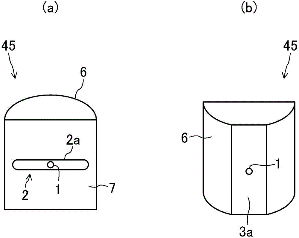
[0108] exist Figure 7 In Modification 2 of the illustrated embodiment, unlike the above-mentioned embodiment, the groove-side oil storage portion 3 of the swing bush 45 is constituted by the circumferential groove 3 extending horizontally along the curved side surface 6 of the swing bush 45 . . That is, the groove-side oil storage portion 3 of the swing bush 45 extends along the sliding direction of the swing bush 45 relative to the groove portion 48 . Both ends of the circumferential groove 3 communicate with the outside of the groove portion 48 of the pistons 40a, 40b.

[0109] According to this modification 2, since the extending direction of the groove-side oil storage portion 3 of the swing bush 45 is aligned with the moving direction of the swing bush 45, the lubricating oil in the groove-side oil storage portion 3 is smoothly drawn. to the outside of the groove portion 48 . Cooling of the sliding surface between the swing bush 45 and the groove portion 48 can be fur...

Deformed example 3-

[0113] exist Figure 8 In Modification 3 of the illustrated embodiment, unlike Modification 2 of the above-mentioned embodiment, the groove-side oil storage portion 3 of the swing bush 45 is a circumference extending horizontally along the curved side surface 6 of the swing bush 45 . To the groove 3, only one end of the circumferential groove 3 is open, and the other end is closed. As described above, even when only one end of the circumferential groove 3 is opened, the lubricating oil in the groove-side oil storage portion 3 can be smoothly discharged to the outside of the groove portion 48 .

[0114] - Modification 4 of Embodiment -

[0115] exist Figure 9 In Modification 4 of the illustrated embodiment, unlike the above-mentioned embodiment, the top of the curved side surface 6 of each swing bush 45a, 45b is cut from the end surface of the swing bush 45a, 45b to the bottom of the oil supply passage 1. near the side. As a result, only one end of the groove-side oil rese...


PUM


Abstract

A rotary compressor is provided with cylinders, pistons, and a pair of bushes (45a, 45b) which sandwiches and supports each blade (35) from both sides, the blades (35) being formed integrally with the cylinders. Either the bush (45a) of the pair and/or the bush (45b) of the pair is provided with: an oil supply passage (1) formed so as to extend from the flat side surface (7) of the bush (45a, 45b) to a curved side surface (6); a blade-side oil holding section (2) to which one end of the oil supply passage (1) is open and which is formed in the flat side surface (7) of the bush (45a, 45b); and a groove-side oil holding section (3) to which the other end of the oil supply passage (1) is open, which is formed in the curved side surface (6) of the bush (45a, 45b), and which has a greater width than the blade-side oil holding section (2).

Description

technical field [0001] The invention relates to a rotary compressor, in particular to a solution for suppressing abnormal wear and seizure of the rotary compressor. Background technique [0002] Heretofore, rotary compressors are known which comprise a bush which supports a piston which rotates eccentrically in a cylinder chamber of a cylinder. In addition, the above-mentioned rotary compressor includes a rotary compressor in which an oil supply passage and an oil storage portion are formed in a bush as disclosed in Patent Document 1. As shown in FIG. [0003] The rotary compressor in Patent Document 1 is a rolling piston compressor. In this rolling piston compressor, a circular groove into which a bush fits is formed in the cylinder, and the vane, which is supported by the bush and can move forward and backward, is integrally formed with the piston. By means of this vane, the cylinder chamber of the cylinder is divided into a high-pressure chamber and a low-pressure chamb...

Claims


Application Information

Patent Timeline
Patent Type & Authority Applications(China)
IPC IPC(8): F04C18/32F04C29/02
CPCF04C18/322F04C29/028F04C18/045F04C2240/56F04C29/02F04C18/32F04C18/063
Inventor 稻田幸博外岛隆造芝本祥孝佐多健一
Owner DAIKIN IND LTD
Why Eureka
Try Eureka