Bottom spraying and air intake control structure of fluidized bed

A technology of control structure and fluidized bed, applied in the direction of powder suspension granulation, etc., can solve problems such as insufficient, and achieve the effect of improving coating efficiency

Inactive Publication Date: 2015-05-06
SHENZHEN XINYITE SCI & TECH
View PDF5 Cites 0 Cited by
  • Summary
  • Abstract
  • Description
  • Claims
  • Application Information

AI Technical Summary

Problems solved by technology

[0002] At present, the fluidized bed is the most commonly used coating technology, and the current air flow distribution plate of the bottom spray of the fluidized bed is a whole. , for a small test machine, the fluidizing air source is enough to generate the wind speed difference inside and outside the guide tube, but it is far from enough for a pilot test or even a large production equipment
[0004] At present, there is no domestic manufacturer of such structural equipment

Method used


Image

  • Bottom spraying and air intake control structure of fluidized bed

Examples


Embodiment 1

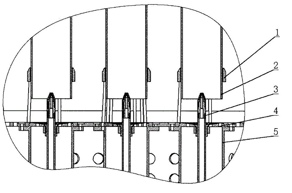
[0014] A kind of air inlet structure at the bottom of the fluidized bed of the present invention as shown in Figure 1, it comprises three spray guns, three guide tubes, three spray guns form an equilateral triangle, the opening of the air flow distribution plate inside the guide tube The porosity is 50%, and the aperture is 0.5mm. The air flow distribution plate outside the guide tube has a porosity of 40%, and the aperture is 1.0mm. Turn on two induced draft fans and set the same speed. The wind speed inside the guide tube is obvious. It is larger than the external wind speed, and this wind speed difference can be adjusted by the fan speed.

Embodiment 2

[0016] A kind of air inlet structure at the bottom of the fluidized bed of the present invention as shown in Figure 1, it comprises five spray guns, five guide tubes, five spray guns form a square and its center, the air flow distribution plate inside the guide tube The opening rate of the airflow distribution plate outside the guide tube is 70%, and the aperture is 0.7mm. The opening rate of the air distribution plate outside the guide tube is 60%, and the aperture is 1.5mm. The wind speed is obviously greater than the external wind speed, and this wind speed difference can be adjusted by the fan speed.


PUM


Abstract

The invention discloses a bottom spraying and air intake control structure of a fluidized bed. The bottom spraying and air intake control structure comprises a flow guide cylinder, an air stream distribution plate, a cavity baffle and two air intake machines. The invention designs a brand new air intake structure, so that the intake air in the flow guide cylinder and intake air outside are separated; individual control can be realized; air speed difference controllable inside and outside the flow guide cylinder is formed, and the fluidized bed of materials can be controlled well, so that a controllable up-down circulation coating is formed. The particular implementation mode is that different aperture ratios and pore diameters are set for air stream distribution plates inside and outside the flow guide cylinder, so that the interior of the flow guide cylinder has relatively high aperture ratio and relatively low pore diameter, and thus relatively high air speed exists in the flow guide cylinder; air speeds inside and outside the flow guide cylinder can be controlled infinitely, so that the favorable fluidization state and the final coating effect are ensured.

Description

technical field [0001] The invention relates to a bottom spray air inlet control structure of a fluidized bed, belonging to the technical field of fluidized bed coating. Background technique [0002] At present, the fluidized bed is the most commonly used coating technology, and the air flow distribution plate of the current fluidized bed bottom spray is a whole. , for a small test machine, the fluidizing air source is enough to generate the wind speed difference inside and outside the draft tube, but it is far from enough for a pilot test or even a large production equipment. [0003] In response to the above problems, we designed a new type of air intake control structure, which improves the wind speed difference inside and outside the guide tube and realizes more convenient regulation. [0004] At present, there is no domestic manufacturer producing such structural equipment. Contents of the invention [0005] The technical problem to be solved by the present inventio...

Claims


Application Information

Patent Timeline
IPC IPC(8): B01J2/16
CPCB01J2/16
Inventor 刘海刘涛张攀峰张宁
Owner SHENZHEN XINYITE SCI & TECH
Why Eureka
Try Eureka