
Car steering lock case mounting bracket

A technology of steering lock shell and mounting bracket, which is applied to steering control, steering column and other directions installed on the vehicle, can solve the problems of unreasonable structural design, complex production process of steering column, single function, etc., and improve the angle adjustment function. , Improve the installation process and achieve a fixed effect

Inactive Publication Date: 2015-05-06
CHONGQING CHANGAN AUTOMOBILE CO LTD
View PDF6 Cites 2 Cited by
  • Summary
  • Abstract
  • Description
  • Claims
  • Application Information

AI Technical Summary

Problems solved by technology

The steering lock housing mounting bracket with this structure has the following problems: (1) The accuracy of the steering column mounting bracket 5 will be affected due to welding heat deformation and the increase in the load bearing of the bracket. The welding of the original bracket body 4 on the steering column mounting bracket 5 will affect the steering column. Angle adjustment function; (2) The original bracket body 4 has a single function and can only play the role of fixing the lock housing. For the fixing of the steering-related wiring harness, another bracket needs to be added, which makes the production process of the steering column complicated; (3) The structural design of the original bracket body 4 is unreasonable, so that the original steering lock housing installation point 6 of the original steering lock housing 20 that cooperates with it (see figure 2 ) is a deep hole, and it is difficult to tighten the fixing screws during installation

Method used


Image

  • Car steering lock case mounting bracket
  • Car steering lock case mounting bracket
  • Car steering lock case mounting bracket

Examples


Embodiment Construction

[0015] The present invention will be described in detail below in conjunction with the drawings.

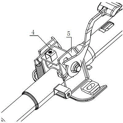
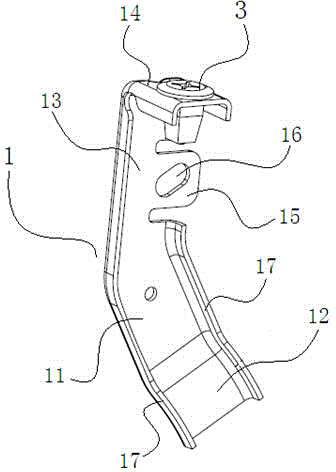
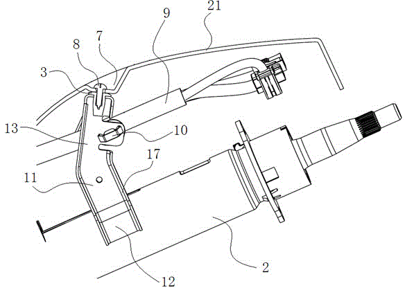
[0016] Such as image 3 , Figure 4 , Figure 5 The illustrated car steering lock housing mounting bracket includes a stamped and formed bracket body 1 with reinforced flanges 17 on the front and rear edges. The bracket body 1 consists of a vertical first support plate 11 and a first support plate 11 The arc-shaped connecting plate 12 that is connected to the lower edge and bent downward to the right, the second support plate 13 that is connected to the upper edge of the first support plate 11 and is bent upward to the right, and is connected to the upper edge of the second support plate 13 And the lock housing installation plate 14 bent to the right is formed, the arc-shaped connecting plate 12 matches and fits the outer circumferential surface of the upper cylinder 2 of the steering column, the lock housing installation plate 14 is provided with a square hole, and the square hole ...


PUM


Abstract

The invention discloses a car steering lock case mounting bracket. The car steering lock case mounting bracket comprises a bracket body formed in a punching mode, and the bracket body is formed by a vertical first supporting plate, an arc-shaped connecting plate, a second supporting plate and a lock case mounting plate, wherein the arc-shaped connecting plate is connected with the lower edge of the first supporting plate and is bent to the lower right portion, the second supporting plate is connected with the upper edge of the first supporting plate and is bent to the upper right portion, and the lock case mounting plate is connected with the upper edge of the second supporting plate and is bent to the right portion. The arc-shaped connecting plate is matched with the outer circumferential face of a steering column upper column casing, a square hole is formed in the lock case mounting plate, a through-hole-type embedding plastic nut is installed in the square hole, a wiring harness fixing plate is formed at the back edge of the second supporting plate in the modes of notch forming and bending, and a strip-type clamping hole is formed in the wiring harness fixing plate. By means of the car steering lock case mounting bracket, a steering lock case can be mounted, a wiring harness can be fixed, and meanwhile influences on the accuracy of the steering column mounting bracket can be avoided.

Description

Technical field [0001] The invention relates to a mounting bracket for automobile parts, in particular to a mounting bracket for an automobile steering lock housing. Background technique [0002] In order to improve driving comfort, automobiles are generally equipped with a steering column angle adjustment function, and the accuracy of the steering column mounting bracket has a decisive influence on the smoothness and quality of the steering column angle adjustment. Such as figure 1 As shown, affected by the traditional design concept, the original bracket body 4 of the existing automobile steering lock housing mounting bracket is in an inverted U shape, and the original bracket body 4 is welded and integrated on the steering column mounting bracket 5. The steering lock housing mounting bracket of this structure has the following problems: (1) The accuracy of the steering column mounting bracket 5 will be affected by the welding thermal deformation and the increase in the bracket...

Claims


Application Information

Patent Timeline
Patent Type & Authority Applications(China)
IPC IPC(8): B62D1/16
CPCB62D1/16
Inventor 郭凯何晨雨王小青张磊光
Owner CHONGQING CHANGAN AUTOMOBILE CO LTD
Features
  • Generate Ideas
  • Intellectual Property
  • Life Sciences
  • Materials
  • Tech Scout
  • Unparalleled Data Quality
  • Higher Quality Content
  • 60% Fewer Hallucinations
Learn More