Gas rail of fuel gas ejector

A gas injector and gas rail technology, which is applied in the field of auto parts, can solve the problem of complex gas injector gas rail structure and processing technology, unreliable combination of intake pipe and external flexible gas pipe, and small cross-section of gas injector gas rail inner cavity and other problems, to achieve the effect of high welding one-time pass rate, improve reliability and stability, and save installation space

Active Publication Date: 2015-05-06
广西淞森车用部件有限公司
View PDF6 Cites 4 Cited by
  • Summary
  • Abstract
  • Description
  • Claims
  • Application Information

AI Technical Summary

Problems solved by technology

[0003] 1. The gas rail of the gas injector is made of casting. In order to ensure a larger inner cavity section, the volume can only be increased. However, due to the limitation of the installation space of the whole machine, the volume cannot be too large, which will lead to the failure of the gas rail of the gas injector. The inner cavity section is too small;
[0004] 2. The gas nozzle seat of the gas injector gas rail is installed on the outer surface of the main gas pipe, the position is high, and the installation space is occupied;
[0005] 3. The structure and processing technology of the gas injector gas rail made by casting are complicated, the production efficiency is low, and the manufacturing cost is high;
[0006] 4. The casting process is prone to defects such as pores, cracks, slag inclusions, and pinholes that are easy to leak, and the product qualification rate is low;
[0007] 5. The combination of the intake pipe and the external soft air pipe is not firm

Method used


Image

  • Gas rail of fuel gas ejector
  • Gas rail of fuel gas ejector
  • Gas rail of fuel gas ejector

Examples


Embodiment Construction

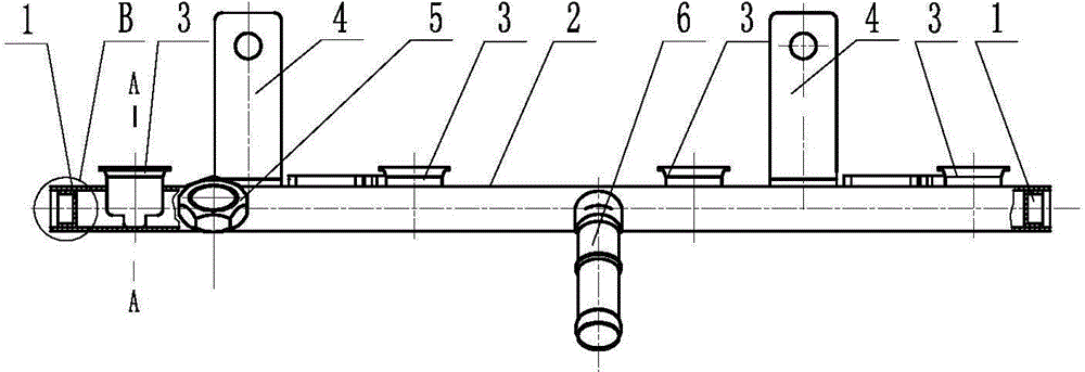
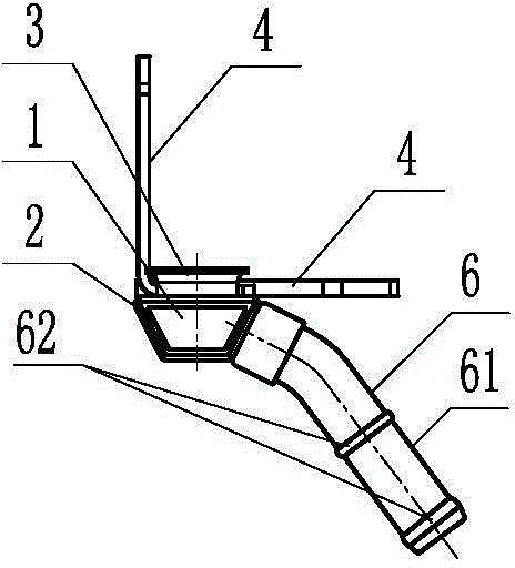
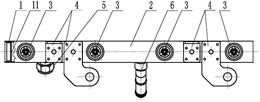
[0026] A gas injector rail, comprising a main air pipe 2, left and right end caps 1, a bracket 4 connected to the main air pipe, an air intake pipe 6, a sensor seat 5 and four uniformly distributed air nozzle seats 3, the left 1. The right end cover 1 is installed at both ends of the main air pipe, the air intake pipe is connected to the external hose, and the gas nozzle seat is connected to the external gas injector; the gas nozzle seat 3 is a cup-shaped structure, and there is a downward protrusion in the middle of the bottom of the cup There are three arc holes 32 evenly distributed on the circular surface at the bottom of the cup; the main air pipe 2 is a stainless steel square pipe, and its cross-sectional shape is an inverted trapezoid with a large upper part and a smaller lower part. There are four valve seat installation holes evenly distributed on the top surface, and the valve seat 3 is welded and fixed in the valve seat installation hole by sinking installation metho...


PUM


Abstract

A gas rail of a fuel gas ejector comprises a main gas pipe, a left end cover, a right end cover, a support, a gas inlet pipe, a sensor base and four evenly distributed gas nozzle bases, wherein the support, the gas inlet pipe, the sensor base and the gas nozzle bases are connected to the main gas pipe. The left end cover and the right end cover are mounted at the two ends of the main gas pipe. The gas inlet pipe is connected with an external hose. The gas nozzle bases are connected with the external fuel gas ejector. Each gas nozzle base is of a cup-shaped structure, wherein the middle of the cup is provided with a circular boss protruding downwards, and three circular arc holes are evenly distributed in the circular ring face of the bottom of the cup. The main gas pipe is a stainless steel square pipe, wherein the cross section of the main gas pipe is in a big-end-up inverted trapezoidal shape, four gas nozzle base mounting holes are evenly distributed in the upper top face of the main gas pipe, and the gas nozzle bases are welded and fixed into the gas nozzle base mounting holes in a sinking installation mode. The sectional area of an inner cavity of the gas rail of the fuel gas ejector is large, the sealing performance is good, the quality is stable and reliable, the installation height can be adjusted flexibly according to the installation space of an engine, and the installation space is saved.

Description

technical field [0001] The invention relates to an automobile part, in particular to a gas injector gas rail of a CNG dual-fuel automobile. Background technique [0002] The gas injector is one of the key devices of the electronically controlled injection system of the gas engine. Its performance directly affects the working performance of the engine. The biggest difference between the gas injector and the general gasoline injector is that it requires a larger flow section to Ensure the passage of large flow of gas; the main problems of the gas injector gas rails currently on the market are: [0003] 1. The gas rail of the gas injector is made of casting. In order to ensure a larger inner cavity section, the volume can only be increased. However, due to the limitation of the installation space of the whole machine, the volume cannot be too large, which will lead to the failure of the gas rail of the gas injector. The inner cavity section is too small; [0004] 2. The gas...

Claims


Application Information

Patent Timeline
Patent Type & Authority Applications(China)
IPC IPC(8): F02M21/02
CPCY02T10/30
Inventor 肖旺卢彦敏林嘉
Owner 广西淞森车用部件有限公司
Why Eureka
Try Eureka