
Wireless module with integrated antenna using hard-soft board

A technology combining board and antenna, applied in antenna support/installation device, structural connection of printed circuit, printed circuit components, etc. Certainty and loss, efficiency and quality, overall size reduction effect

Active Publication Date: 2017-11-14
UNIVERSAL SCIENTIFIC INDUSTRIAL (SHANGHAI) CO LTD +1
View PDF2 Cites 0 Cited by
  • Summary
  • Abstract
  • Description
  • Claims
  • Application Information

AI Technical Summary

Problems solved by technology

[0003] At present, the commonly used wireless module is to set the communication chip and the antenna on a single printed circuit board, but this design will produce a large volume, which is not conducive to setting the antenna at the best position for sending and receiving wireless signals, so it is difficult to apply to small of electronic products
Therefore, manufacturers have developed another commonly used wireless module, which separates the communication chip and the antenna, and then uses a high-frequency connector (RF Connector) and a cable to connect the two, although it is beneficial to match the internal space of the electronic product and can Set the antenna at the best position, but the above-mentioned high-frequency connectors and cables must use special materials and designs to reduce high-frequency loss, which will greatly increase the cost of parts, although it can be replaced by a pin connector (Pin Connector) The aforementioned high-frequency connectors and cables can reduce high-frequency loss, but the matching impedance problem during signal transmission will still increase the difficulty of design
[0004] In view of the aforementioned problems, US8344955 discloses a wireless module, the communication chip and the antenna are respectively arranged on a rigid circuit board (Rigid PCB) and a flexible circuit board (Flexible PCB), and at least a part of the aforementioned flexible circuit board is combined with the rigid circuit board One end of the board forms a circuit board structure similar to a rigid-flex PCB (Rigid-Flex PCB), but its power layer (Power Layer) and ground layer (Ground Layer) are discontinuously segmented between the rigid circuit board and the flexible circuit. On the board, in addition to increasing the complexity of the circuit, it may also introduce unnecessary noise, so there is still a need for improvement

Method used


Image

  • Wireless module with integrated antenna using hard-soft board
  • Wireless module with integrated antenna using hard-soft board

Examples


Embodiment Construction

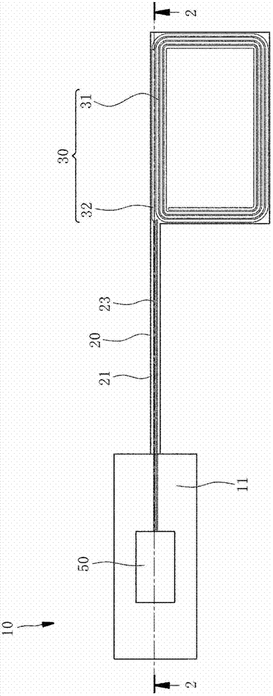
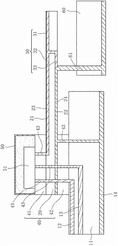
[0023] In order to clearly illustrate the technical characteristics of the present invention, please refer to figure 1 and figure 2 , the wireless module 10 of a preferred embodiment provided by the present invention includes: a flexible substrate 20, an antenna 30 disposed on one side of the flexible substrate 20, and the other side of the flexible substrate 20 that is far away from the antenna 30 and is stacked and bonded. Two rigid substrates 41 & 42 on one side, and a communication unit 50 disposed on the rigid substrate 41 . The specific structures of the aforementioned components are described in detail below.

[0024] The flexible substrate 20 has a first surface 21 and a second surface 22 opposite to each other, and the aforementioned surfaces 21 & 22 are respectively provided with a conductive signal layer 23 and a ground layer 24 .

[0025] The antenna 30 is disposed on the first surface 21 of the flexible substrate 20. In this embodiment, a Near Field Communicati...


PUM


Abstract

A wireless module, comprising a flexible substrate, an antenna disposed on one side of the flexible substrate and electrically connected to the signal layer and the ground layer of the flexible substrate, and a second antenna stacked and bonded to the side of the flexible substrate relatively far away from the antenna. A rigid substrate, and at least one communication unit arranged on the first rigid substrate and electrically connected to the signal layer; therefore, the aforementioned flexible substrate and the first rigid substrate together form a rigid-flexible board, and the signal layer and the ground layer are continuously arranged on the On the same flexible substrate, it helps to reduce the uncertainty and loss on the high-frequency signal transmission path, and at the same time reduces the cost of parts, facilitates antenna optimization, and helps to reduce the overall size.

Description

technical field [0001] The present invention is related to the built-in wireless module of electronic products, specifically refers to a rigid-flex board (Rigid-Flex Board) to integrate the antenna and communication chip into a single module, with small size, low loss, low Advantages of cost, ease of design, and ease of optimization. Background technique [0002] With the advancement of science and technology, various handheld electronic products are rapidly popularized, and are developing towards high integration and small size. The communication modules built in electronic products are also inevitably developing towards the same trend. [0003] At present, the commonly used wireless module is to set the communication chip and the antenna on a single printed circuit board, but this design will produce a large volume, which is not conducive to setting the antenna at the best position for sending and receiving wireless signals, so it is difficult to apply to small of electro...

Claims


Application Information

Patent Timeline
Patent Type & Authority Patents(China)
IPC IPC(8): H01Q1/22H05K1/14
Inventor 陈信宏施瑞坤刘益诚
Owner UNIVERSAL SCIENTIFIC INDUSTRIAL (SHANGHAI) CO LTD
Learn More