Supercharge Your Innovation With Domain-Expert AI Agents!

Conductive contact piece and electrical connection contact strip with same

A technology of conductive contact piece and contact piece, applied in the direction of contact parts, etc., can solve the problems of poor contact consistency, large contact resistance, affecting conductivity, etc. Effect

Active Publication Date: 2015-05-06
济南致通电气有限公司
View PDF9 Cites 9 Cited by
  • Summary
  • Abstract
  • Description
  • Claims
  • Application Information

AI Technical Summary

Problems solved by technology

However, the contact area between the tip of the contact finger and the plug is a point contact, resulting in a large contact resistance, which limits its flow performance, and the conductive contact at the bottom is formed by riveting and bending the embedded groove Yes, it belongs to the secondary processing process, so the consistency of the contacts formed by it is poor, and it also has an adverse effect on the contact resistance, that is, it affects its electrical conductivity

Method used


Image

  • Conductive contact piece and electrical connection contact strip with same
  • Conductive contact piece and electrical connection contact strip with same
  • Conductive contact piece and electrical connection contact strip with same

Examples


Embodiment 1

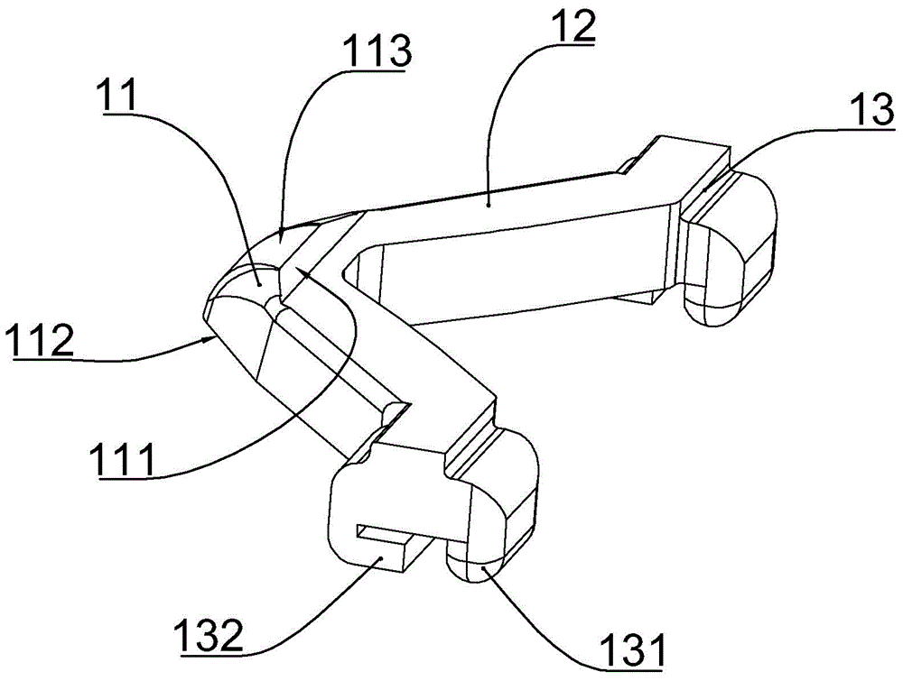
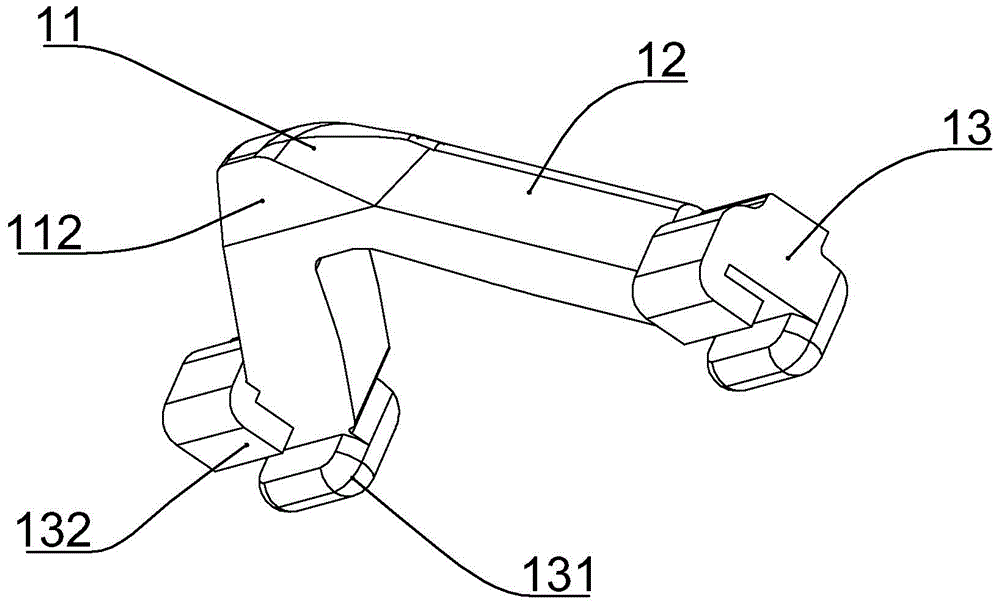
[0024] according to Figure 1 to Figure 2 As shown, the conductive contact piece of this embodiment includes a top conductive end 11, two symmetrically arranged conductive arms 12 integrally connected to the top conductive end, and a bottom conductive end 13 integrally connected to the end of the conductive arm. The upper end surface of the above-mentioned top conductive terminal is a top conductive contact 113 whose contact area is in a line shape, and the line-shaped contact area is parallel to the connecting line of the two bottom conductive terminals.

[0025] The top conductive contact overall has an arc-shaped surface, and the line-shaped contact area is located on the arc-shaped surface. In this way, when the movable contact is in contact with the contact area of ​​the top conductive contact, the contact area can always be kept in a line shape.

[0026] A riveting edge 132 and a bottom conductive contact 131 opposite to the riveting edge are integrally connected below ...

Embodiment 2

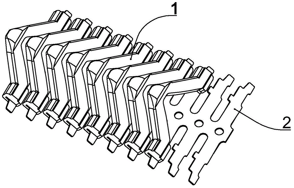
[0031] to combine Figure 1 to Figure 6 As shown, the electrical connection contact strip of this embodiment includes one or more conductive contact strips 1 described in Embodiment 1, and also includes an elastic steel strip 2; both sides of the elastic steel strip are connected with equal intervals. The torsion arm 25 of integral structure, the elastic steel band is positioned at the position between every two relative torsion arms and is provided with assembly location hole 20, and the torsion angle of torsion arm is 15-20 degree, and the riveting edge 132 of described conductive contact piece and The outer end of the torsion arm is riveted and fixed.

[0032] The side of the torsion arm 25 close to the outer end is formed with a bottom conductive contact limiting opening 24 that is positioned in cooperation with the bottom conductive contact 131 on the conductive contact piece. The bottom conductive contact 131 cooperates with the bottom conductive contact limit opening 2...

Embodiment 3

[0037] The planar electrical connector of this embodiment has adopted the contact strip described in Embodiment 2, as Figure 7 As shown, the contact strip is installed on the static contact 4, and the movable contact 3 and the top conductive contact 113 are in close contact with each other due to the elasticity of the elastic steel strip. Similarly, the static contact 4 and the bottom conductive contact Point 131 close contact.


PUM


Abstract

The invention discloses a conductive contact piece and an electrical connection contact strip with the same. The conductive contact piece comprises a top conducting end, two symmetrical conducting arms integrally connected with the top conducting end and two bottom conducting ends integrally connected to the ends of the conducting arms. The upper end face of the top conducting end is a top conductive contact with a contact area being linear, and the linear contact area is parallel to a connecting line of the two bottom conducting ends. A riveting edge and a bottom conductive contact opposite to the riveting edge are arranged under each bottom conducting end. By the top conductive contact with the linear contact area, the conductive contact piece is matched with a moving contact to form a linear electrical contact area, and contact resistance is reduced.

Description

technical field [0001] The invention belongs to the field of electrical connector structures, and in particular relates to a conductive contact piece structure of the electrical connector. Background technique [0002] The invention patent application with the publication number "CN103985994A" discloses a conductive contact finger and watch strap connector and its manufacturing method, wherein the embedded groove of the conductive contact finger has an included angle with the tip of the contact finger and the contact finger arm so that The arm of the contact finger is in close contact with the plug, and the arrangement distance of the installation strips ensures that the contact fingers will not interfere with each other, thus ensuring the stability of the current output and improving the service life of the strap connector. However, the contact area between the tip of the contact finger and the plug is a point contact, resulting in a large contact resistance, which limits i...

Claims


Application Information

Patent Timeline
IPC IPC(8): H01R13/02H01R13/24
CPCH01R13/02H01R13/24
Inventor 林小平
Owner 济南致通电气有限公司
Features
  • R&D
  • Intellectual Property
  • Life Sciences
  • Materials
  • Tech Scout
  • Unparalleled Data Quality
  • Higher Quality Content
  • 60% Fewer Hallucinations
Learn More