Phase changing control method and phase changing control device

A technology with the largest trigger delay angle, applied in the field of electric power, which can solve the problems of converter blocking and converter commutation failure.

Active Publication Date: 2015-05-06
NR ELECTRIC CO LTD +1
View PDF4 Cites 22 Cited by
  • Summary
  • Abstract
  • Description
  • Claims
  • Application Information

AI Technical Summary

Problems solved by technology

[0004] However, when a large transient disturbance occurs in the DC transmission system, the scheme of determining the maximum trigger delay angle provided by the related technology will cause the commutation failure of the converter or even cause the converter to be locked.

Method used


Image

  • Phase changing control method and phase changing control device
  • Phase changing control method and phase changing control device
  • Phase changing control method and phase changing control device

Examples


Embodiment Construction

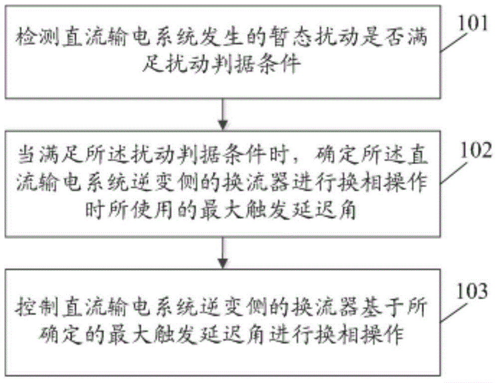
[0090] In order to make the object, technical solution and advantages of the present invention clearer, the present invention will be further described in detail below in conjunction with the accompanying drawings and embodiments. It should be understood that the specific embodiments described here are only used to explain the present invention, not to limit the present invention.

[0091] In the process of implementing the present invention, the inventor found that the following method is used in the related art to determine the maximum trigger delay angle for the commutation process of the converter on the inverter side:

[0092]

[0093] Among them, γ o is the reference value of arc extinguishing angle, d x is the relative inductive voltage drop, I o is the DC current command value, I d is the actual DC current on the inverter side of the DC transmission system, I dN is the rated DC current on the inverter side of the DC transmission system, U di0N is the rated idea...


PUM


Abstract

The invention discloses a phase changing control method and a phase changing control device. The method comprises the steps of detecting whether the transient disturbance of a DC power distribution system satisfies a disturbance criterion condition, when the transient disturbance satisfies the disturbance criterion condition, determining the maximum trigger delay angle of a current converter on the inversion side of the DC power distribution system during the phase changing operation, and then controlling the current converter on the inversion side of the DC power distribution system to perform the phase changing operation based on the determined maximum trigger delay angle, wherein the determined maximum trigger delay angle is smaller than the maximum trigger delay angle used before the transient disturbance. According to the phase changing control method, the corresponding maximum trigger delay angle can be determined according to the degree of the transient disturbance of the DC power distribution system, and therefore, the phase changing margin can be guaranteed and the failure in phase changing in case of great transient disturbance can be avoided.

Description

technical field [0001] The invention relates to electric power technology, in particular to a commutation control method and a commutation control device. Background technique [0002] On the inverter side of the DC transmission system, the converter performs commutation processing according to the maximum trigger delay angle. The physical process by which electrical current is transferred from one current path to another. [0003] In the related technology, the DC voltage and DC current of the converter are guaranteed to have a positive slope relationship by using the DC current command value to determine the commutation voltage drop and introducing a positive slope coefficient K. When a small transient disturbance occurs in the DC transmission system, the DC The current command value remains unchanged, and the actual DC current increases due to the disturbance. At this time, if the maximum trigger delay angle determined in the related technology is larger than the maximum...

Claims


Application Information

Patent Timeline
Patent Type & Authority Applications(China)
IPC IPC(8): H02J3/36H02M7/48
CPCH02J3/36H02M7/48H02J3/24Y02E60/60H02J1/00H02M1/44H02M7/12H02M7/155H02J3/02H02M1/4208H02M3/33507
Inventor 卢东斌王永平王振曦王俊生潘卫明
Owner NR ELECTRIC CO LTD
Why Eureka
Try Eureka