
Closed motor outer wind shield

A closed-type, windshield technology, which is applied in the field of outer windshields, can solve the problems of insufficient utilization of external air passages, increased costs, fan loss and heating, etc., and achieve the effect of improving cooling effect, reducing the number of cooling pipes, and reducing the temperature of inlet air

Inactive Publication Date: 2015-05-06
泰豪沈阳电机有限公司
View PDF0 Cites 1 Cited by
  • Summary
  • Abstract
  • Description
  • Claims
  • Application Information

AI Technical Summary

Problems solved by technology

Blow-in air cooling air passes through the fan first and will be heated by the fan loss
Moreover, this structure does not make full use of the external air duct. When the loss is large, the motor needs to use more copper and silicon steel sheets to ensure the temperature rise of the motor, which leads to an increase in cost.

Method used


Image

  • Closed motor outer wind shield
  • Closed motor outer wind shield

Examples


Embodiment Construction

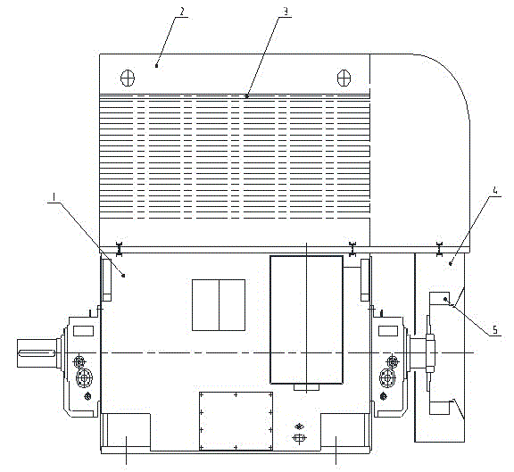
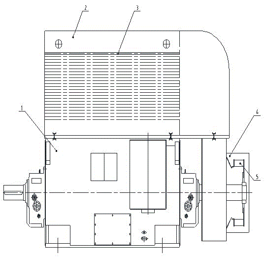
[0011] The centrifugal fan on the side of the outer wind cover of this patent is running, and the outside air is drawn into the outer wind cover from the other side through the air guide plate of the cooling pipe, and discharged to the surroundings through the outer wind cover and the outer fan, so that there is air flow in the cooling pipe. , which greatly increases the surface area of ​​heat exchange, improves the utilization rate of external cooling air, and can more effectively reduce the temperature rise of the motor.


PUM


Abstract

The invention discloses a closed motor outer wind shield comprising a motor outer wind shield and an outer fan. The closed motor outer wind shield is structurally characterized in that a pull-out cooling wind path is adopted, and cooling air in the cooling wind path first passes through a cooler, then the outer wind shield, and finally the outer fan. Cooling air loss and heating by the fan are avoided, the cooling effect of the cooler can be improved, the mechanical loss of a main motor can be reduced, and the overall material cost of the motor is lower than the cost of the original cooling device.

Description

technical field [0001] This patent relates to a closed motor outer wind cover, in particular to an outer wind cover which adopts a draw-out type external air path to improve the utilization rate of the motor external cooling air. Background technique [0002] The heat generation of the enclosed motor will reduce the service life, and the main parts of the heat generation are the stator and rotor windings. Therefore, the inside of the motor is enclosed and an internal fan is installed on the rotor shaft. The motor drives the internal fan to form an internal circulation inside the motor, and the heat exchange through the cooling tube of the cooler reduces the temperature rise inside the motor. At present, the general box-type motor is equipped with an external fan on the closed external rotor shaft. The motor runs to drive the external fan, and the external air is directly sent to the cooling pipe through the external windshield to reduce the temperature of the cooling pipe...

Claims


Application Information

Patent Timeline
Patent Type & Authority Applications(China)
IPC IPC(8): H02K9/06
CPCH02K9/06
Inventor 王欣彤
Owner 泰豪沈阳电机有限公司
Learn More