Switchgear for controlling the energy supply of electric motor connected thereto

A switchgear and energy supply technology, applied in electric switches, high-voltage/high-current switches, deceleration devices of AC motors, etc., can solve the problems of switch wear and limited quantity, improve switch characteristics, and reduce additional hardware consumption , the effect of increasing the number of operating cycles

Active Publication Date: 2015-05-06
SIEMENS AG
View PDF8 Cites 6 Cited by
  • Summary
  • Abstract
  • Description
  • Claims
  • Application Information

AI Technical Summary

Problems solved by technology

By switching off the power supply and automatically opening the switch, a breaking arc is formed at the switch, wh

Method used


Image

  • Switchgear for controlling the energy supply of electric motor connected thereto

Examples


Embodiment Construction

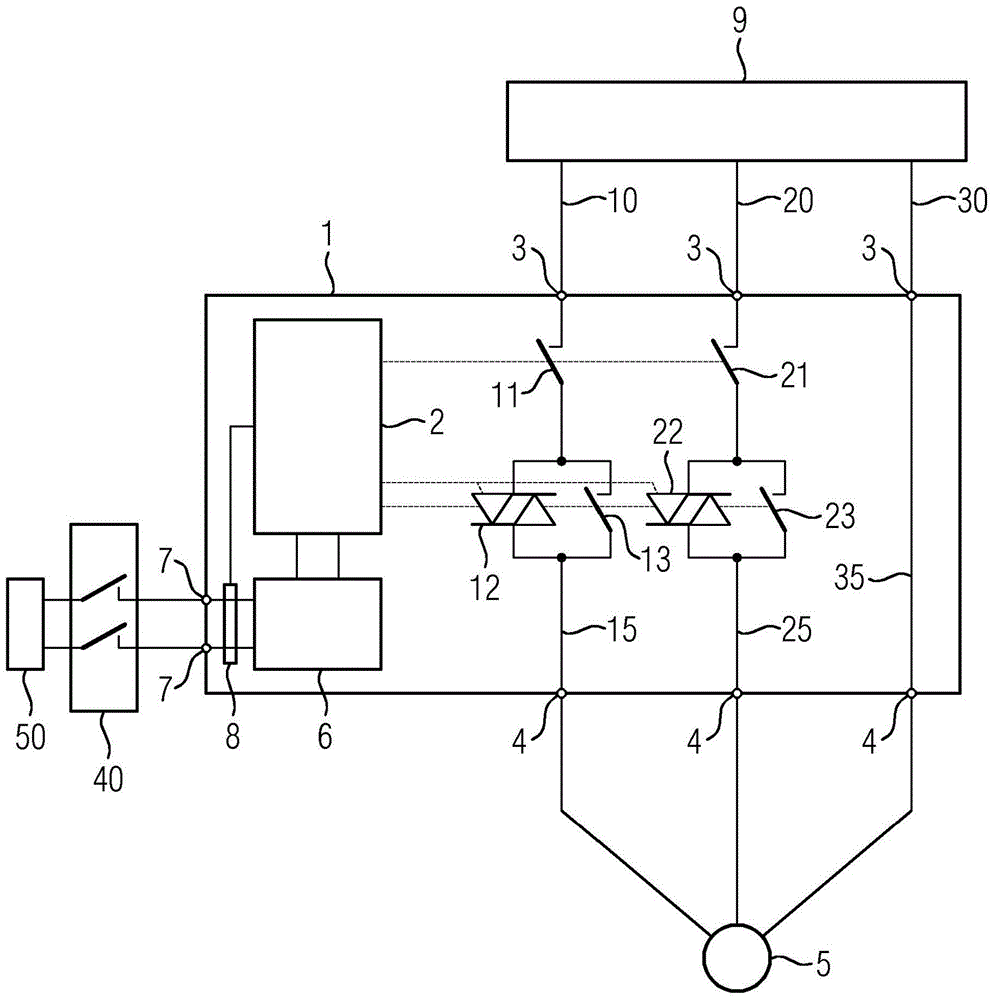
[0035] The drawing shows a schematic diagram of a system for safely operating an electric machine 5 . The system comprises a power supply network 9 , a motor 5 , a switchgear 1 , a power source 50 and an emergency stop switchgear 40 .

[0036] The switching device 1 is connected to the supply network 9 with its three connection points 3 on the input side and to the electric machine 5 with its three connection points 4 on the output side. Motor 5 is an asynchronous motor. The power supply network 9 is a three-phase AC network for industrial low-voltage switchgear. The switching device 1 is a motor starter 1 , by means of which the energy supply to a downstream electric motor 5 can be controlled.

[0037] The first phase 10 of the supply network 9 is connected by means of a conductor to the connection point 3 on the input side and leads within the device via a first current path 15 of the motor starter 1 to the connection point 4 on the output side and subsequently by means of...


PUM


Abstract

The invention relates to a switchgear (1) which comprises a control unit (2), a supply connection (7) and a first current path (15), the first current path (15) comprising a first electromechanical switch (11) and, connected in series to the first switch (11), a parallel connection of a second electromechanical switch (13) to a semiconductor switch (12). In order to make a switchgear (1) available which allows an increased number of switching operations, the switchgear (1) comprises an energy accumulator (6) and a measuring device (8), the control unit (2) being capable of monitoring, by means of the measuring device (8), the energy supply coming in through the supply connection (7). The control unit (2) is designed such that, if the energy supply coming in through the supply connection (7) reaches a critical range, it controls the output of the switching signals by means of the energy of the energy accumulator (6) such that: in a first step, the semiconductor switch (12) is switched to be electrically conducting and the second switch (13) is then opened, and in a second step following the first step, the semiconductor switch (12) is switched to be electrically non-conducting and the second switch (11) is then opened.

Description

technical field [0001] The invention relates to a switchgear and a method for a switchgear. The switching device according to the invention is used in particular within the framework of industrial automation technology. In particular, the switchgear is a motor starter. Background technique [0002] An electric machine connected downstream of the switching device can be controlled by means of the switching device. For this purpose, the electric machine connected downstream of the switching device is supplied with energy via the switching device, so that the electric machine is connected to the supply network. In particular, the power supply network is the low-voltage network of an industrial facility (for example three-phase, 400 Volts, 50 Hz). [0003] In order to control the energy supply of a downstream electric motor, the switching device comprises a control unit and a first current path. Via the first current path, the first phase of the supply network is conducted t...

Claims


Application Information

Patent Timeline
IPC IPC(8): H01H33/59H02P1/02H02P3/22H02P29/02
CPCH01H9/541H02P3/22H02P29/025H02H3/08
Inventor 迪尔克·赫兹马尔科·舍嫩伯格约翰·塞茨斯特凡·齐茨勒
Owner SIEMENS AG
Why Eureka
Try Eureka