Switchgear for controlling the energy supply of an electric motor connected downstream

A switchgear and energy supply technology, applied in the direction of electric switches, circuits, electrical components, etc., can solve the problems of wear at the switch, limit the number of switchgear, etc., achieve the effect of improving energy buffering and increasing the number of operating cycles

Active Publication Date: 2017-05-10
SIEMENS AG
View PDF5 Cites 0 Cited by
  • Summary
  • Abstract
  • Description
  • Claims
  • Application Information

AI Technical Summary

Problems solved by technology

By disconnecting the power supply and automatically opening the switch, a switch-off arc is formed at the switch, which causes severe wear at the switch, thereby generally limiting the number of such operating cycles of the switchgear

Method used


Image

  • Switchgear for controlling the energy supply of an electric motor connected downstream

Examples


Embodiment Construction

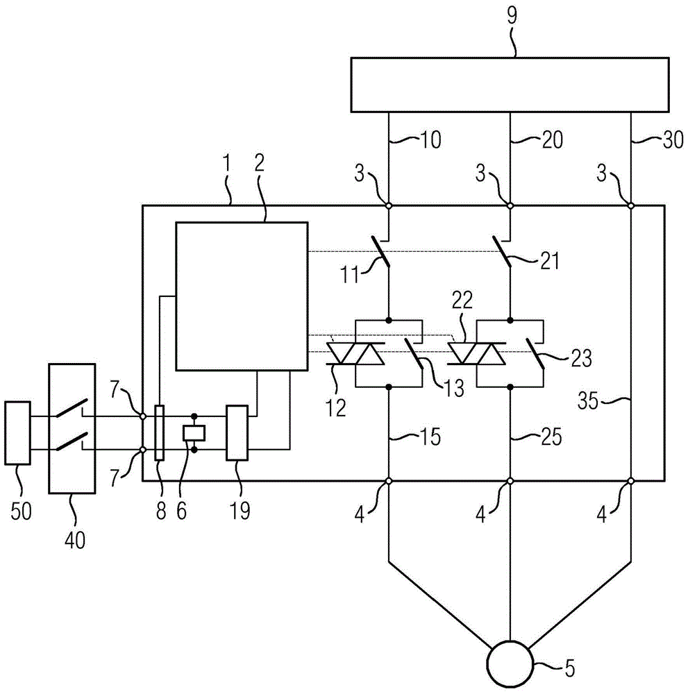
[0040] The drawing shows a schematic diagram of a system for the safe operation of an electric machine 5 . The system comprises a power supply network 9 , a motor 5 , a switchgear 1 , a power supply 50 and an emergency stop switchgear 40 .

[0041] The switching device 1 is connected by means of its three input-side connection points 3 to the supply network 9 and by means of its output-side connection points 4 to the electric machine 5 . Motor 5 is an asynchronous motor. The power supply grid 9 is the three-phase AC grid of industrial low-voltage switchgear installations. The switching device 1 is a motor starter 1 by means of which the power supply to a downstream electric motor 5 can be controlled.

[0042] The first phase 10 of the supply network 9 is connected to the connection point 3 on the input side by means of a line and is led within the device via the first current path 15 of the motor starter 1 to the connection point 4 on the output side and then by means of oth...


PUM


Abstract

The invention relates to a switching device (1) with a control unit (2), a power supply interface (7), a power supply unit (19) and a first current path (15) comprising an electromechanical first switch ( 11) and a parallel circuit of an electromechanical second switch (13) and a semiconductor switch (12) in series with the first switch (11). In order to provide a switchgear (1) with an increased number of operating cycles, it is proposed that the switchgear (1) comprises an energy store (6) and a measuring device (8) connected to the control unit (2), wherein the energy store ( 6) Intermediate connection between the supply connection (7) and the supply unit (19), wherein the control unit (2) can be connected by means of the measuring device (8) in the area between the supply connection (7) and the supply unit (19) Monitoring of the energy supply to the switchgear via the power supply interface (7), wherein the control unit (2) is designed such that when the energy supply monitored by means of the measuring device (8) falls into a critical region, the control unit by means of Energy from the energy store (6): Conductively connect the semiconductor switch (12) in a first step and subsequently disconnect the second switch (13), after the first step connect the semiconductor switch non-conductively in a second step (12) and then open the first switch (11).

Description

technical field [0001] The invention relates to a switching device for controlling the energy supply of a downstream electric machine and to a method for the switching device. The switching device according to the invention is in particular a motor starter and is used in particular in industrial automation technology. An electric machine connected downstream of the switching device can be controlled by means of the switching device. For this purpose, the energy supply to the electric machine connected downstream of the switching device is conducted via the switching device so that the electric machine is connected to the power supply network. Low-voltage power grids (e.g. three-phase, 400 Volt, 50 Hz) of power supply networks, especially industrial installations. Background technique [0002] In order to control the energy supply to the downstream connected electric machine, the switching device comprises a control unit and a first current path. Via the first current path...

Claims


Application Information

Patent Timeline
Patent Type & Authority Patents(China)
IPC IPC(8): H01H9/54H02P1/02H02P3/02
CPCH01H9/542H02H7/085
Inventor 胡贝特·库拉安德烈亚斯·弗里奇斯特凡·格鲁贝尔
Owner SIEMENS AG
Why Eureka
Try Eureka