
A split-type melting glue device

A split-type, glue injection device technology, applied in the field of glue injection, can solve the problems of long waiting time, lower glue viscosity, several hours or dozens of hours, etc., to reduce waiting time, reduce volume, and shorten heating the effect of time

Active Publication Date: 2017-05-10
SUZHOU KONIG ELECTRONICS TECH CO LTD
View PDF6 Cites 0 Cited by
  • Summary
  • Abstract
  • Description
  • Claims
  • Application Information

AI Technical Summary

Problems solved by technology

Due to the integrated structure, the glue tank is heated as a whole. The current melt tank has the following defects: the melting speed is slow, resulting in too long a waiting time before production; Only a few grams to more than ten grams, a large amount of glue has been waiting for use, most of the glue has been heated repeatedly for a long time, and the glue formed by melting all the glue often takes several hours or dozens of hours to fully Exhausting energy not only wastes energy, but also causes carbonization of the glue due to long-term heating; the carbonized glue blocks the flow channel of the glue, causing appearance defects of the injection molded product, and the reduced viscosity of the carbonized glue causes poor functionality of the encapsulated product change

Method used


Image

  • A split-type melting glue device
  • A split-type melting glue device
  • A split-type melting glue device

Examples


Embodiment Construction

[0020] The preferred embodiments of the present invention will be described in detail below in conjunction with the accompanying drawings, so that the advantages and features of the present invention can be more easily understood by those skilled in the art, so as to define the protection scope of the present invention more clearly.

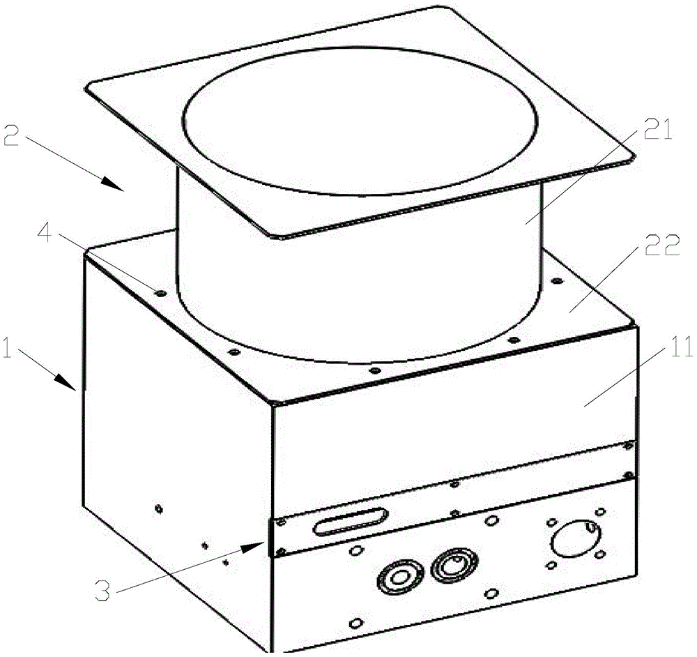
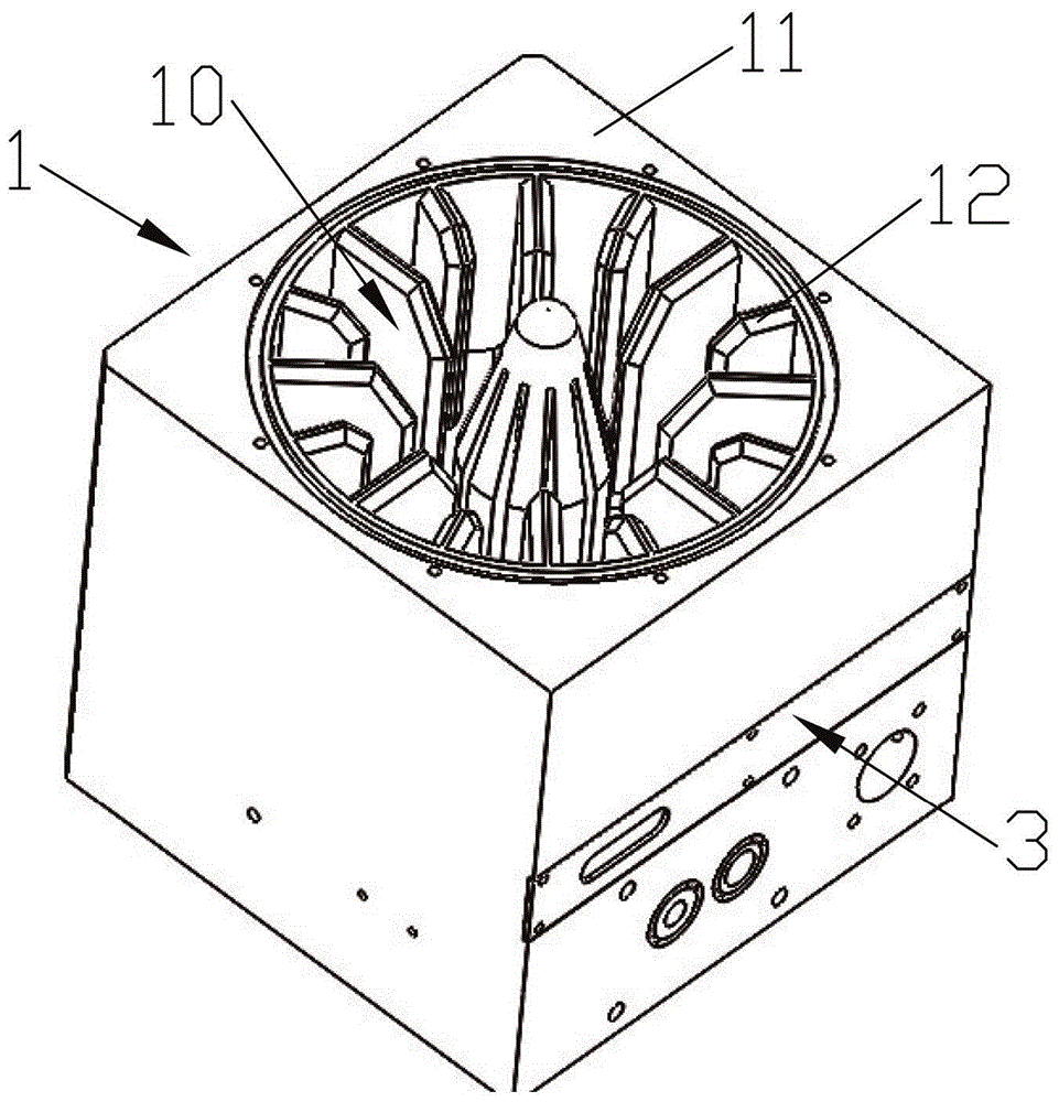
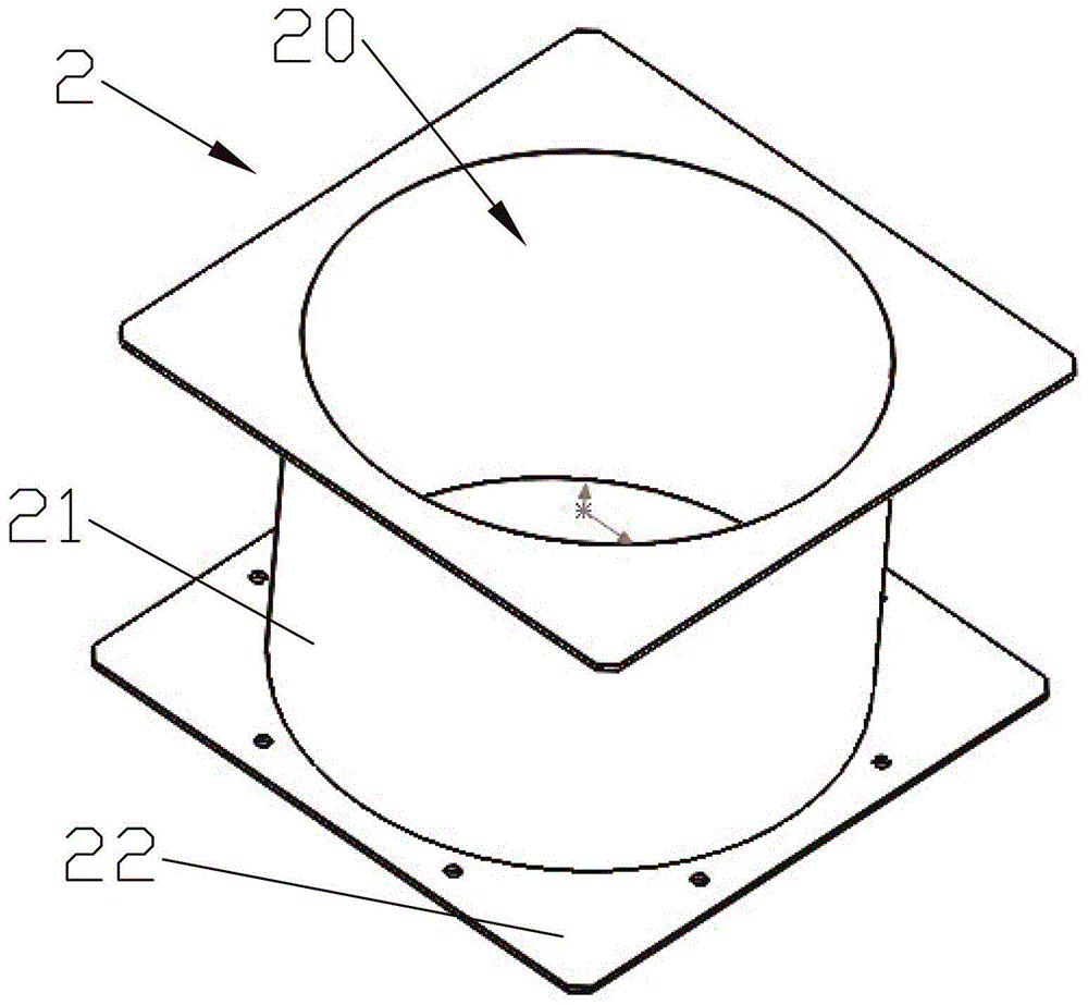
[0021] Refer to attached figure 1 to attach image 3 As shown, a split-type glue melting device includes a melt glue tank 1 for melting rubber materials, a heating device 3 arranged on the glue melt tank 1, and a tank 2 to be melted for storing glue materials. The melt glue tank 1 is made of aluminum alloy, and the to-be-melted tank 2 is made of a material whose thermal conductivity is lower than that of aluminum alloy. The melt tank 1 is connected with the tank 2 to be melted, the melt tank 1 is formed with a melt space 10, the tank 2 to be melted is formed with a storage space 20, and the melt space 10 is located in the storage The melt space...


PUM


Abstract

The invention discloses a split-type glue melting device which comprises a glue melting cylinder (1) used for melting glue, a heating device (3) arranged on the glue melting cylinder (1), and a to-be-molten glue cylinder (2) used for storing the glue, wherein the glue melting cylinder (1) is made of aluminum alloy; the to-be-molten glue cylinder (2) is made of metal or alloy with a heat conduction coefficient smaller than that of aluminum alloy; the glue melting cylinder (1) is connected with the to-be-molten glue cylinder (2); a glue melting space (10) is formed in the glue melting cylinder (1); a storage space (20) is formed in the to-be-molten glue cylinder (2); the glue melting space (10) is positioned below the storage space (20) and communicated with the storage space (20). The invention aims to provide the split-type glue melting device which can shorten the waiting time before production and avoid carbonization in a glue melting process.

Description

technical field [0001] The invention relates to the field of glue injection, in particular to a split glue melting device. Background technique [0002] In the prior art, a glue melting machine generally consists of a glue tank base and a glue barrel. The base of the glue tank and the rubber barrel are connected by welding or fastening with bolts to form a glue tank. The glue melter is heated by the heat pipe installed at the bottom of the glue tank, and the heat is conducted to the glue melt tank through the heating grid welded on the base of the glue tank and the glue tank barrel in turn. Since the base of the glue tank is integrated with the rubber barrel, when the heat pipe of the base of the glue tank is heated, all the rubber materials in the glue tank are heated and melted as a whole. Due to the integrated structure, the glue tank is heated as a whole. The current melt tank has the following defects: the melting speed is slow, resulting in too long a waiting time be...

Claims


Application Information

Patent Timeline
Patent Type & Authority Patents(China)
IPC IPC(8): B05C11/10B05C11/11
Inventor 朱建晓
Owner SUZHOU KONIG ELECTRONICS TECH CO LTD
Learn More