
Wooden box notching machine

A technology of corner cutting machine and wooden frame, which is applied in the direction of wood processing equipment, manufacturing tools, mitering working devices, etc., can solve the problems of low defective or scrap rate, high corner cutting efficiency, low processing efficiency, etc., and achieve defective products Or the effect of low scrap rate, high corner cutting precision and high corner cutting efficiency

Inactive Publication Date: 2015-05-13
YIWU WADOU PICTURE
View PDF9 Cites 6 Cited by
  • Summary
  • Abstract
  • Description
  • Claims
  • Application Information

AI Technical Summary

Problems solved by technology

[0006] The invention solves the defects that the traditional angle cutting machine needs the middle pad to assist in cutting the first end, remove the pad to cut the second end, troublesome operation and low processing efficiency, and provides a wooden frame angle cutting machine, which can directly position and cut the angle without Pad block, easy to operate, high corner cutting efficiency
[0007] The invention also solves the defects that the middle block of the traditional corner cutting machine is easy to wear, affects the corner cutting accuracy, and has a high rate of defective or scrap products, and provides a wooden frame corner cutting machine that does not need a cushion block, has high corner cutting precision, and has no defective or defective products. Low scrap rate
[0008] The present invention also solves the defect that the existing traditional angle cutting machine needs intermediate pads to assist in angle cutting, and can only cut one wooden strip at a time, which has low efficiency. It provides a wooden frame angle cutting machine that can simultaneously cut multiple wooden strips at one time Corner cutting, high cutting efficiency

Method used


Image

  • Wooden box notching machine
  • Wooden box notching machine
  • Wooden box notching machine

Examples


Embodiment

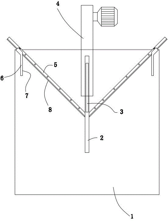
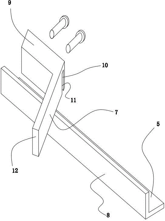
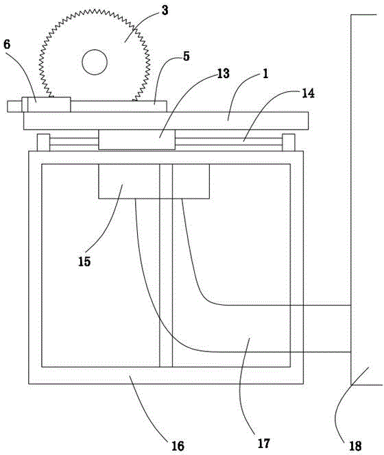
[0027] Embodiment: a kind of wooden frame chamfering machine (see attached figure 1 attached image 3 ), including a frame 16 on which a working table 1 and a cutting tool 4 that can slide relative to the frame are arranged.

[0028] Cutting knife is fixed on the frame, and cutting knife comprises cutting knife 3 and drives the motor that cutting knife rotates. The top of frame is fixed with two parallel guide shafts 14 by bearing, and guide shaft is parallel to cutting knife, and the lower surface of worktop is fixed with guide sleeve 13, and guide sleeve is sleeved on the guide shaft. A slit 2 is arranged on the working table, the width of the slit is adapted to the thickness of the cutting knife, and the position of the slit corresponds to the cut position.

[0029] Two mutually perpendicular retaining bars 5 are fixed on the work table, and the symmetrical lines of the two retaining bars coincide with the cutting knife. The retaining bar is angle steel, one side of the ...


PUM


Abstract

The invention relates to a wooden box notching machine which solves the problems that according to a traditional notching machine, a middle cushion block needs to be used for assisting to cut a first end, the cushion block is dismounted to cut a second end, operation is troublesome, and the processing efficiency is low. A baffle bar is fixedly arranged on a working table, the baffle bar is provided with a baffle face perpendicular to the working table, a cutting knife of a cutting tool is perpendicular to the working table, an angle formed by the cutting knife and the baffle face is 45 degrees, and a gap allowing the cutting knife to pass through is formed in the working table. A positioning block is connected to the baffle bar, the positioning block is provided with a positioning surface perpendicular to the working table, an angle formed by the positioning surface and the baffle face is 45 degrees, and the positioning surface is parallel to the cutting knife. The positioning block is mounted on the baffle bar, and the length of the positioning block is determined. One side edge of a wood bar is in contact with the baffle face, one end of the wood bar is in butt joint with the positioning surface, the other end of the wood bar is notched, as long as the wood bar and the baffle face are not separated, the cut end is at an angle of 45 degrees, and the cushion block is of no need. Operation is convenient, the notching precision is high, and the rate of inferior-quality products or defective products is low.

Description

technical field [0001] The invention relates to a corner cutting device, in particular to a wooden frame corner cutting machine capable of accurately ensuring a 45° angle. Background technique [0002] Although there are frameless decorative paintings now, their backs still need to be supported by wooden frames. The frame is basically square, and there are relatively few frames formed at one time. Most of the wooden frames and plastic frames need to be cut by a wooden frame corner cutter, and then made by a corner nailing machine. That is, each wooden strip needs to be cut at an angle of 45°, so that the picture frame made is beautiful. [0003] The existing wooden frame angle cutting machine cuts a 45° angle by fixing a positioning block with a 45° angle on the stopper. When cutting the angle for the first time, a piece of the same 45° angle needs to be glued on the surface of the 45° angle. For the pads with an angle of °, when the second angle is cut, the wooden block w...

Claims


Application Information

Patent Timeline
IPC IPC(8): B27G5/04
CPCB27G5/04
Inventor 龚新明
Owner YIWU WADOU PICTURE
Learn More