Screw material conveyor

A technology for conveyors and conveying mechanisms, applied in the directions of transportation and packaging, loading/unloading, containers, etc., which can solve the problems of high warehouse pressure, increased warehouse pressure, and high energy consumption, and achieve low warehouse pressure, low resistance feeding, The effect of reducing energy consumption

Inactive Publication Date: 2015-05-13
ZHEJIANG ZOKSEN ENVIRO ENERGY EQUIP
View PDF15 Cites 2 Cited by
  • Summary
  • Abstract
  • Description
  • Claims
  • Application Information

AI Technical Summary

Problems solved by technology

[0002] During the feeding process of the biomass feeding system of a biomass power plant, the material is fed through the rotation of the screw shaft in the multi-head screw feeding unit, but during the transportation process, when encountering biomass such as straw and straw, due to the characteristics of the And warehouse pressure and other reasons, there will be arching of materials and increased warehouse pressure, which will have a great impact on the continuous feeding of equipment, and the warehouse pressure is too large, which requires a high-power reducer and high energy consumption.

Method used


Image

  • Screw material conveyor
  • Screw material conveyor
  • Screw material conveyor

Examples


Embodiment Construction

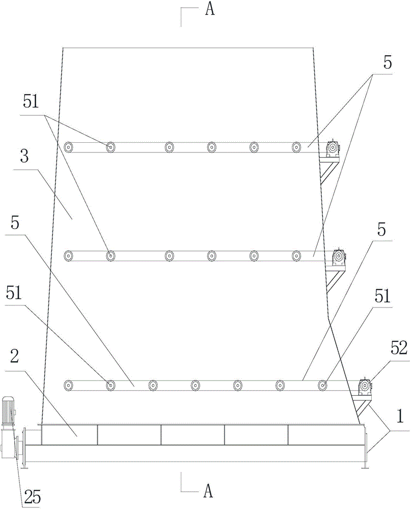
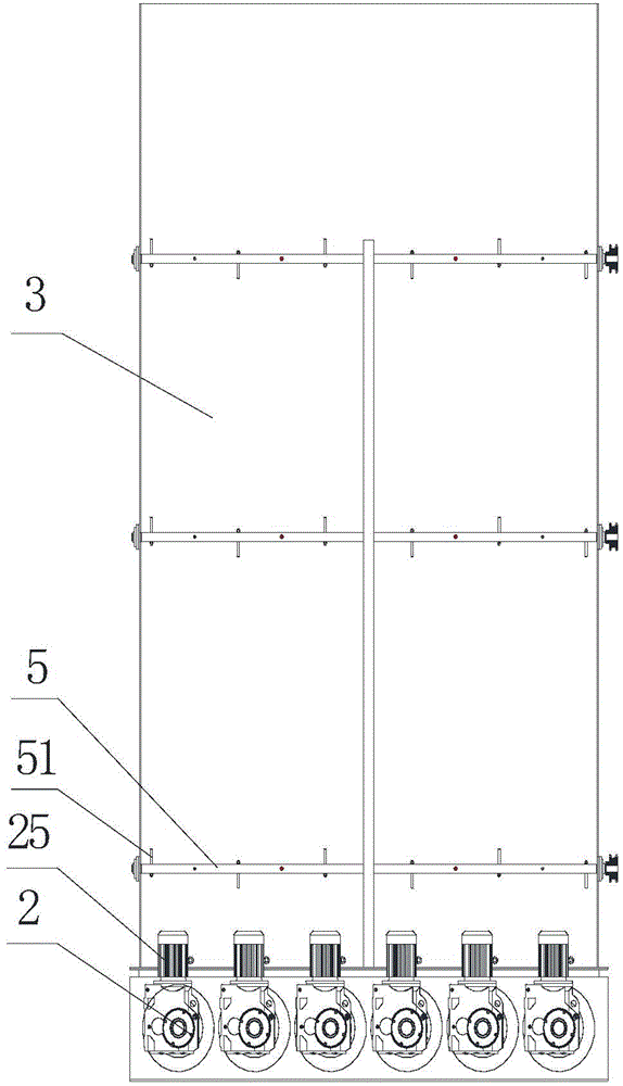
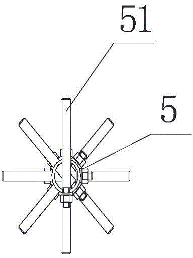
[0017] Such as Figures 1 to 5 Shown is a kind of embodiment of screw material conveyor of the present invention, and it comprises body 1, and described body 1 is provided with feed bin 3, and the bottom of feed bin 3 is provided with conveying mechanism 2 in body 1, and conveying mechanism 2 has conveying screw 22. There is a stirring shaft 5 inside the silo 3, and a motor 52 that drives the stirring shaft 5 to rotate is provided on the frame 1. A number of stirring rakes 51 are arranged on the stirring shaft 5, and the stirring rakes 51 are eccentrically installed on the stirring shaft. On the shaft 5, the axial direction of the stirring shaft is perpendicular to the axial direction of the conveying screw, the conveying mechanism 2 includes a housing 21, an arc-shaped groove is arranged in the housing 21, and the conveying screw 22 is shaftless Screw, the conveying screw 22 is located in the groove, and the housing 21 is provided with anti-arching parts for preventing the co...


PUM


Abstract

The invention discloses a screw material conveyor, the arching phenomenon of material occurs in the conveying process can be solved, and the influence to continuous feeding of equipment is avoided. The screw material conveyor comprises a conveyor body, a stock bin is arranged in the conveyor body, conveying mechanisms are arranged below the stock bin which is in the conveyor body, and the conveying mechanisms are provided with conveying screws; stirring shafts are arranged in the stock bin, the stirring shafts are all provided with multiple stirring rake rods, and the stirring rake rods are arranged on the stirring shafts in an eccentric mode; the axial directions of the stirring shafts are perpendicular to the axial directions of the conveying screws, each conveying mechanism comprises a shell, an arc groove is formed in the shell, the conveying screws are all shaftless screws, and the conveying screws are located in the corresponding grooves; anti-arching portions used for preventing the conveying screws from arching are arranged above the two sides of each groove of the corresponding shell, and the conveying screws are limited in intervals enclosed by the anti-arching portions and the grooves.

Description

technical field [0001] The invention relates to a material conveying device, in particular to a screw material conveying machine. Background technique [0002] During the feeding process of the biomass feeding system of a biomass power plant, the material is fed through the rotation of the screw shaft in the multi-head screw feeding unit, but during the transportation process, when encountering biomass such as straw and straw, due to the characteristics of the Due to reasons such as warehouse pressure and other reasons, there will be arching of materials and increased warehouse pressure, which will have a great impact on the continuous feeding of equipment, and the warehouse pressure is too large, requiring a high-power reducer and high energy consumption. Contents of the invention [0003] The technical problem to be solved by the present invention is to provide a screw material conveyor, which can solve the phenomenon of material arching during the conveying process, avo...

Claims


Application Information

Patent Timeline
Patent Type & Authority Applications(China)
IPC IPC(8): B65G65/46B65D88/68
CPCB65G65/46B65D88/68
Inventor 钱尧翎
Owner ZHEJIANG ZOKSEN ENVIRO ENERGY EQUIP
Why Eureka
Try Eureka