
A low-strength fiber pulling and cutting device

A technology of strong fiber, pulling and cutting and making sliver, applied in the direction of fiber bundles into fiber sliver/yarn, etc., can solve the problems of difficult carding of low-strength functional fibers, etc., to reduce the pulling force and reduce the pulling force Effect

Active Publication Date: 2019-04-19
QINGDAO UNIV
View PDF8 Cites 0 Cited by
  • Summary
  • Abstract
  • Description
  • Claims
  • Application Information

AI Technical Summary

Problems solved by technology

[0008] Aiming at the deficiencies of the existing technology, the technical problem to be solved by the present invention is to provide a method to solve the deficiencies of the existing drawing-cutting technology and equipment capacity, and the reality that low-strength functional fibers are difficult to carding, and effectively obtain Low-strength fiber cotton-type staple fiber, reducing fiber loss, accurately controlling the blending ratio, and improving the quality of yarn blending. Low-strength fiber traction cutting device

Method used

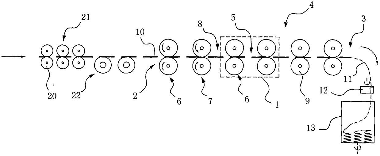
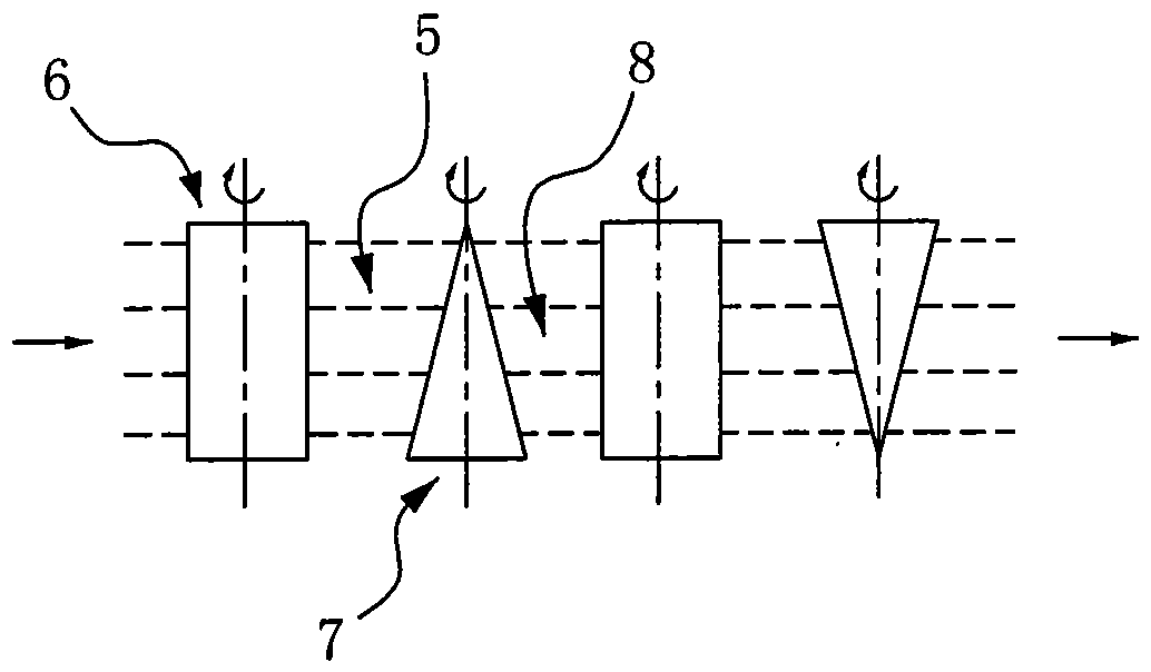

Image

  • A low-strength fiber pulling and cutting device
  • A low-strength fiber pulling and cutting device
  • A low-strength fiber pulling and cutting device

Examples


Embodiment 1

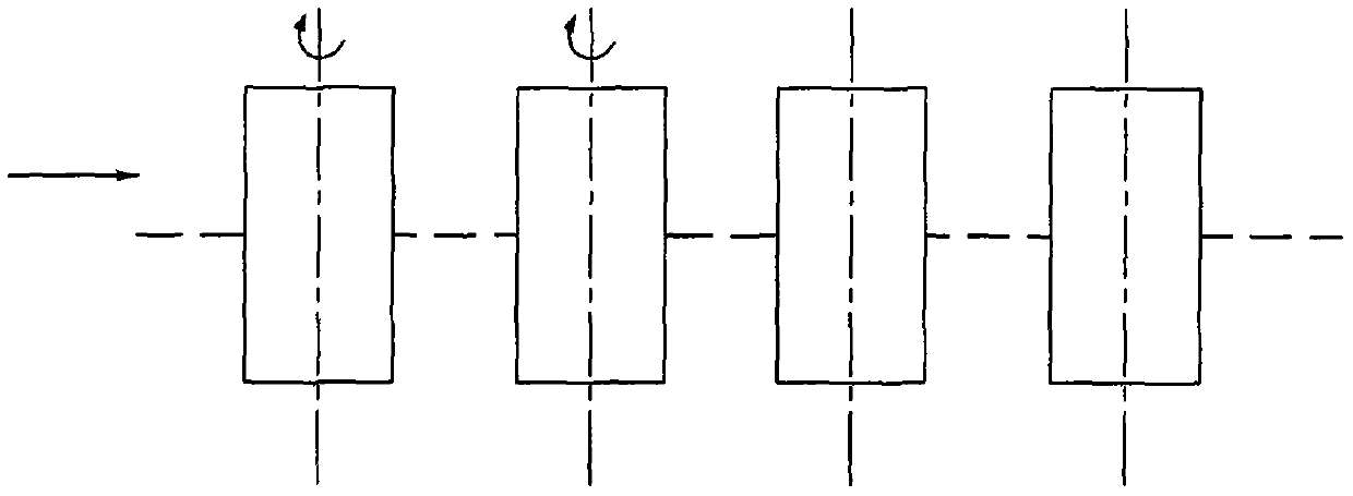
[0036] Such as figure 1As shown in , it is a schematic diagram of the structure of the traditional pulling roller group, such as figure 2 , 3 As shown, a low-strength fiber stretching and stripping device includes a stretching device 4 with a feed end 2 and a discharge end 3 composed of multiple sets of stretching rolls 1, and each set of stretching rolls 1 respectively form a stretching area 5, each group of stretching rolls 1 is composed of a pair of drafting rolls 6 and stretching rolls 7 that mesh with each other, the stretching between adjacent stretching rolls 1 A drafting transition zone 8 is formed between the cutting roll 7 and the drafting roll 6, and the drafting roll 6 and the drafting roll 7 are both composed of two roller bodies 9 meshing with each other, and the drafting in each drafting zone 5 The horizontal distance along the axial direction of the roller body 9 between the roller 6 and the cutting roller 7 gradually increases or decreases gradually. In th...

Embodiment 2

[0043] The same parts of this embodiment and Embodiment 1 will not be repeated, and the difference is that: Figure 4 As shown, the axial longitudinal cross-sectional shape of the roll body 15 of the stretching roll 14 is set as a trapezoidal structure. The roller bodies 15 of the adjacent stretching rollers 14 are arranged parallel to each other and opposite to each other.

Embodiment 3

[0045] The same parts of this embodiment and Embodiment 1 will not be repeated, and the difference is that: Figure 5 As shown, the horizontal distance between the drafting roller 17 and the drafting roller 18 in each drafting zone 16 along the axial direction of the roller body 19 changes alternately. The longitudinal cross-sectional shape of the roll body 19 of the stretching roll 18 in the axial direction is configured as a wave structure.


PUM

PropertyMeasurementUnit
lengthaaaaaaaaaa

Abstract

The invention discloses a low-strength fiber stretch-breaking and slivering device. The low-strength fiber stretch-breaking and slivering device comprises a stretch-breaking device which is composed of multiple sets of stretch-breaking roller set and provided with a feeding end and a discharging end, a stretch-breaking area is formed between each set of the stretch-breaking roller set, each set of the stretch-breaking roller set is composed of a pair of stretching rollers and a pair of stretch-breaking rollers which are meshed with each other respectively, a stretch-breaking transition area is formed by the stretching roller and the stretch-breaking roller which are located between adjacent stretch-breaking roller sets, the stretching roller and the stretch-breaking roller are both composed of two roller bodies, and the size of the horizontal distance between the stretching roller and the stretch-breaking roller in the axial direction of the roller body in each stretch-breaking area is changeable. Through arranging tapered or trapezoid structure, the tractive force of the stretch-breaking areas is greatly reduced, the diameters of the stretch-breaking rollers are decreased, the distance of the stretch-breaking areas formed by the stretch-breaking roller sets is shortened, the distance between the stretching roller and the stretch-breaking roller can be set to be small enough, stretch-breaking can be conducted on short fiber with smaller cotton fiber level, and the production efficiency is greatly improved. The low-strength fiber stretch-breaking and slivering device has the advantages that the structure is simple and compact, the occupied area is small, the cost is low, and popularization and application are applicable.

Description

technical field [0001] The invention belongs to the technical field of textile machinery, and in particular relates to a low-strength fiber stretch cutting device. Background technique [0002] As we all know, the existing spinning process generally needs to go through fiber bundle slitting, blending, and then obtain thick fibers with corresponding fiber ratios, and then further process fine fibers to be used as textile spun yarns. There are usually two ways to make fiber bundle slivers. That is, cutting and stretching. Isometric fibers are usually made by a special cutting machine. The length of the fibers is equal, and there are cotton-type staple fibers and medium-length fibers. Cotton-type staple fiber has various specifications of 33mm, 35mm, 38mm, and 41mm; medium-length chemical fiber has various specifications of 45mm, 51mm, 60mm, and 65mm. The different long fiber is made by the stretch cutting method, because the products processed by the different long fiber have...

Claims


Application Information

Patent Timeline
Patent Type & Authority Patents(China)
IPC IPC(8): D01G1/08
CPCD01G1/08
Inventor 马建伟陈韶娟孙永军李杨
Owner QINGDAO UNIV
Learn More