A two-stage vortex dry vacuum pump

A dry vacuum pump and scroll technology, applied in the direction of rotary piston pumps, rotary piston/swing piston pump components, rotary piston machinery, etc., can solve the problem that the compression ratio and ultimate vacuum cannot be improved, and the application effect is limited and other problems, to achieve the effect of improving the compression ratio and ultimate vacuum degree and meeting the requirements of use

Active Publication Date: 2015-05-13
NORTHEASTERN UNIV +1
View PDF6 Cites 5 Cited by
  • Summary
  • Abstract
  • Description
  • Claims
  • Application Information

AI Technical Summary

Problems solved by technology

[0004] Whether domestic or foreign, the most widely used scroll dry vacuum pump is the double-sided scroll dry vacuum pump, which can be roughly divided into two types. One is that the scroll working chambers on both sides of the vacuum pump are on the outer circumference side. The air inlets are connected, and the vortex working chambers on both sides of the vacuum pump are connected to the exhaust port at the center side, so the two vortex working chambers on both sides are equivalent to parallel work. Although the pumping speed of the vacuum pump can be effectively improved, it cannot Improve the compression ratio and ultimate vacuum; the other is that the scroll working chamber on one side of the vacuum pump communicates with the air inlet on the center side, and there is a ventilation gap on the outer circumference side between the scroll fixed plate and the scroll moving plate, which is in contact with the intake port. The vortex working chamber with the air ports communicated with the other vortex working chamber through the air gap, and the other vortex working chamber communicates with the exhaust port at the center side, so the two vortex working chambers on both sides are equivalent to series connection. Although it has some effect on increasing the pumping speed and increasing the compression ratio, the actual application effect is still very limited.

Method used


Image

  • A two-stage vortex dry vacuum pump
  • A two-stage vortex dry vacuum pump

Examples


Embodiment Construction

[0017] The present invention will be further described in detail below in conjunction with the accompanying drawings and specific embodiments.

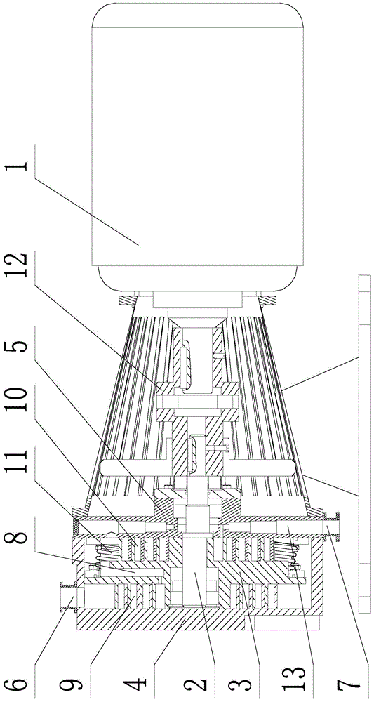
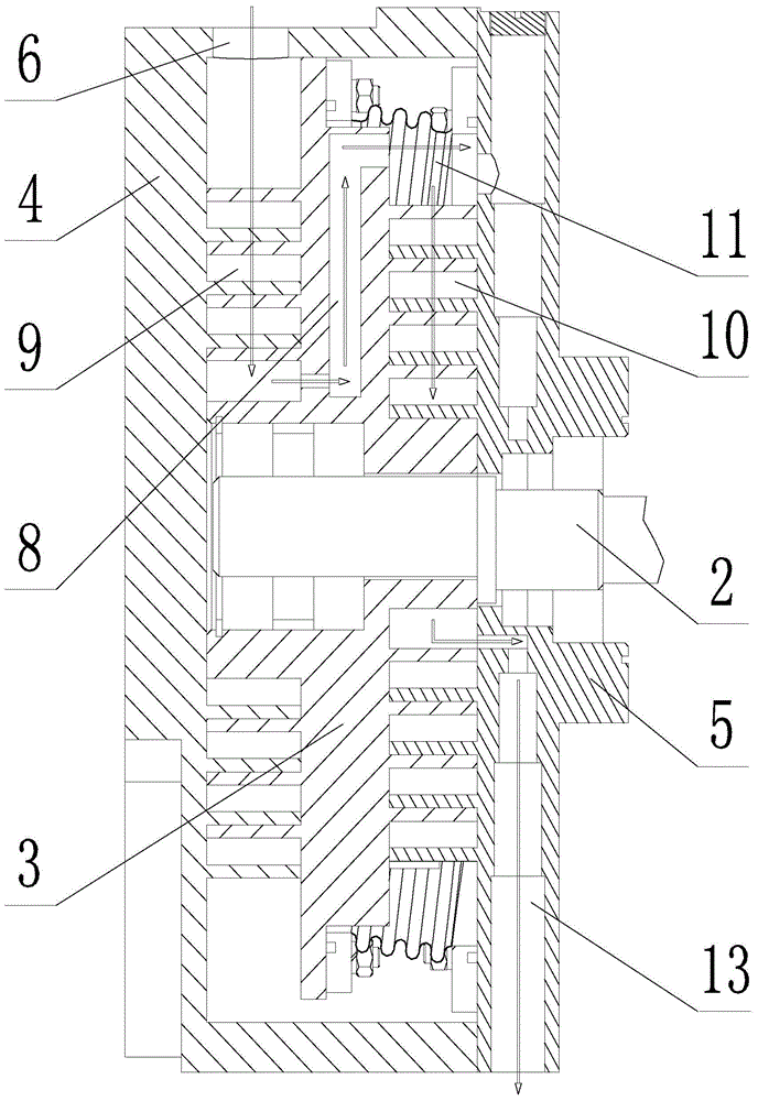
[0018] Such as figure 1 As shown, a two-stage scroll dry vacuum pump includes a motor 1, a crankshaft 2, a scroll movable disk 3, a left scroll fixed disk 4 and a right scroll fixed disk 5, the motor shaft of the motor 1 and the crankshaft 2 The main shaft end of the main shaft is connected by a coupling 12. The scroll movable disk 3 is set on the eccentric part of the crankshaft 2. The scroll movable disk 3 adopts a double-sided scroll structure. The left scroll fixed disk 4 and the scroll The left side disk of the moving disk 3 cooperates, the right scroll fixed disk 5 cooperates with the right side disk of the scroll movable disk 3, the left scroll fixed disk 4 and the right scroll fixed disk 5 are sealed and connected on the outer circumference side, and the left scroll fixed disk 5 cooperates with the right scroll disk. The comp...


PUM


Abstract

A two-stage vortex dry vacuum pump is disclosed. The outer circumferential side of a first vortex working cavity is communicated with an air inlet in a left vortex fixed disc. At least one airflow channel is disposed along the radial direction in a vortex moving disc. One end of each airflow channel is communicated with the center side of the first vortex working cavity, and the other end is communicated with the outer circumferential side of a second vortex working cavity. The center side of the second vortex working cavity is communicated with an air discharging channel and an air discharging port in a right vortex fixed disc. The outer circumferential side of the vortex moving disc and the outer circumferential side of the right vortex fixed disc are hermetically connected through a corrugated pipe. The outer circumferential side of the first vortex working cavity and the outer circumferential side of the second vortex working cavity are sealed and separated by the corrugated pipe. The corrugated pipe, the vortex moving disc and the right vortex fixed disc are connected through flanges or welding. The two-stage vortex dry vacuum pump breaks the limitation on the compression ratio and the final vacuum of two-side vortex dry vacuum pumps at present, and increases the compression ratio and the final vacuum of the vacuum pump by two-stage continuous compression of the two vortex working cavities connected in series.

Description

technical field [0001] The invention belongs to the technical field of dry vacuum pumps, in particular to a two-stage scroll dry vacuum pump. Background technique [0002] Dry vacuum pumps generally refer to the -2 It is a vacuum pump that works in the pressure range of Pa and below, does not use any oil and liquid in the suction flow channel, and can continuously exhaust directly to the atmosphere. Driven by the semiconductor industry, chemical engineering and other industries, dry vacuum pumps have developed rapidly. At present, there are many types of dry vacuum pumps, including multi-stage claw type, multi-stage Roots type, Roots + claw type combination, screw type and scroll type etc. [0003] Among them, the scroll type, namely the scroll dry vacuum pump, evolved from the scroll compressor and belongs to the positive displacement vacuum pump. Because the scroll dry vacuum pump has clean and oil-free, wide working pressure range, reliable performance and small torque ...

Claims


Application Information

Patent Timeline
Patent Type & Authority Applications(China)
IPC IPC(8): F04C18/02F04C23/00F04C25/02
CPCF04C18/0215F04C23/02F04C25/02F04C29/12
Inventor 岳向吉巴德纯陆艳君张英莉刘坤王光玉张振厚毛励珩
Owner NORTHEASTERN UNIV
Why Eureka
Try Eureka