Power rotation heater

A technology of power rotation and heater, which is applied in the direction of heating devices and other non-combustion heat generation, to achieve the effects of reducing heating costs, improving heating efficiency, and improving safety and reliability

Inactive Publication Date: 2015-05-13
丹东丹联仪表检测技术研究有限公司
View PDF5 Cites 23 Cited by
  • Summary
  • Abstract
  • Description
  • Claims
  • Application Information

AI Technical Summary

Problems solved by technology

[0003] The technical problem to be solved by the present invention is to provide a dynamic rotary heater to solve the problem of heating some fuel oil, lubricating oil, flammable, explosive and highly toxic substances during work and operation in the fields of petroleum, chemical industry, and large machinery

Method used


Image

  • Power rotation heater

Examples


Embodiment Construction

[0015] In order to make the object, technical solution and advantages of the present invention clearer, the present invention will be further described in detail below in conjunction with the accompanying drawings and embodiments. It should be understood that the specific embodiments described here are only used to explain the present invention, not to limit the present invention.

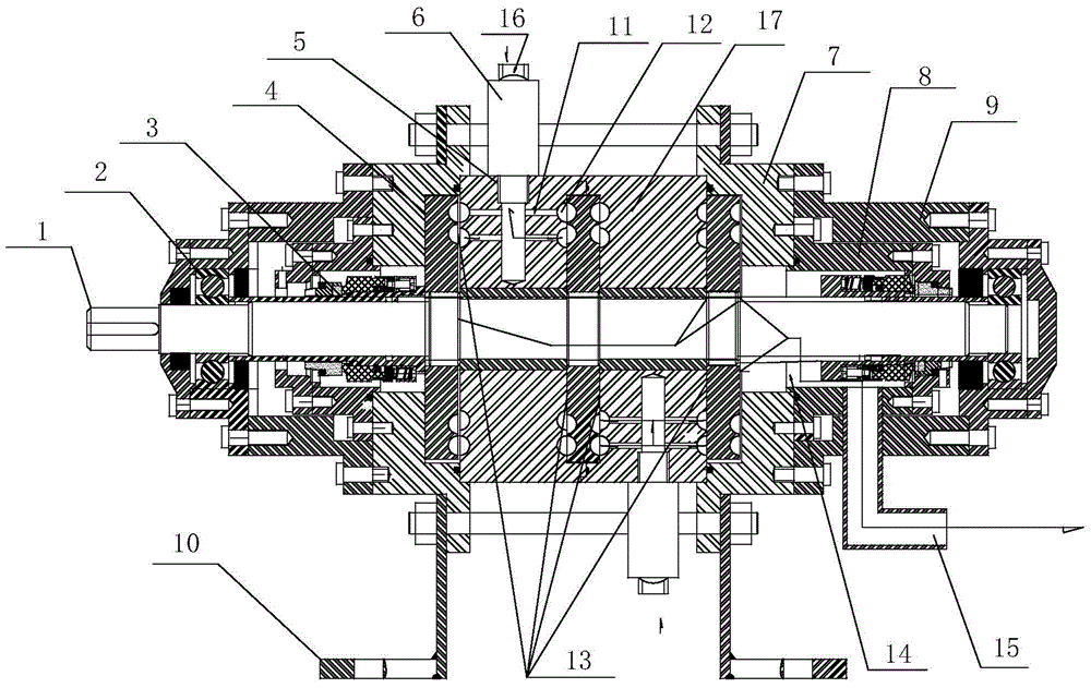
[0016] see figure 1 , a power rotary heater, the heater includes a plurality of liquid cavitation tubes 6, a stator 17 and three rotors 4, the stator 17 and the three rotors 4 pass through the drive shaft 1, so that the stator 17 and the drive shaft 1 are left There are gaps, and the three rotors 4 are respectively arranged at the two ends of the stator 17 and the middle inside of the stator 17, there is a gap 13 between the rotor 4 and the stator 5, and a plurality of stator liquid inlet holes 5 with one end opening are arranged on the stator 17, each The stator liquid inlet hole 5 is connected t...


PUM


Abstract

The invention relates to heating use of flammable, explosive and toxic liquid and gas and the like in the field of petroleum, chemical engineering, large machines and the like, belongs to the field of heating equipment on hot water heating occasions and the like, and relates to a power rotation heater. The power rotation heater comprises multiple liquid cavitation pipes. A drive shaft penetrates through a stator and multiple rotors coaxially. A gap is formed between the stator and the drive shaft. The rotors are at least arranged at the two ends of the stator, wherein gaps are formed between the rotors and the stator. Multiple stator liquid inlets are formed in the stator, wherein one end of each stator liquid inlet is open. Each stator liquid inlet is connected with the corresponding liquid cavitation pipe. Branch pipes are arranged in the stator. The gaps between the stator and the rotors and the stator liquid inlets are communicated through the branch pipes. Liquid with heat flows to a liquid outlet through the gaps, liquid cavitation pipe liquid inlets are connected through heating pipelines, and a circulation is formed. The purpose that the flammable, explosive and toxic liquid is not heated by naked fire and electric power is achieved, kinetic energy is converted into heat energy through a rotary power machine, immersion effluent is eliminated, and safety and reliability are improved.

Description

technical field [0001] The invention belongs to the field of heating equipment used for heating flammable, explosive, highly toxic liquids and gases in the fields of petroleum, chemical industry, and large machinery, and can also be used in places such as hot water heating, and particularly relates to a dynamic rotary heater . Background technique [0002] Petroleum, chemical industry, large-scale machinery and other fields need to heat some fuel oil, lubricating oil and flammable, explosive and highly toxic substances during work and operation, especially in winter. If an open flame is used for heating, firstly, it consumes a lot of energy, secondly, it pollutes the environment, and thirdly, the heating efficiency is low. With electric heating, it is difficult to provide a large power supply on site. Contents of the invention [0003] The technical problem to be solved by the present invention is to provide a dynamic rotary heater to solve the problem of heating some fu...

Claims


Application Information

Patent Timeline
Patent Type & Authority Applications(China)
IPC IPC(8): F24J3/00
Inventor 田树梁
Owner 丹东丹联仪表检测技术研究有限公司
Why Eureka
Try Eureka