Sign pen emission circuit of infrared electronic white board

A technology of signal transmission and electronic whiteboard, applied in the direction of digital data processing, input/output process of data processing, instruments, etc. The effect of precise writing, stable energy and avoiding misoperation

Inactive Publication Date: 2015-05-13
四川中时代科技股份有限公司
View PDF0 Cites 1 Cited by
  • Summary
  • Abstract
  • Description
  • Claims
  • Application Information

AI Technical Summary

Problems solved by technology

[0002] The classroom is an important position in school education, and the blackboard is an indispensable tool for classroom teaching. It is used to present teaching content and organize teaching activities. Because blackboards are cheap and easy to use, blackboards have spread throughout all schools and classrooms. However, as With the continuous progress of society, the defects of the blackboard have become more and more obvious to us, so multimedia teaching has emerged as the times require. However, the projection teaching method of the large screen also has many shortcomings. The teacher cannot modify the content of the large screen at any time. The large screen The content is relatively fixed and lacks flexibility
Nowadays, interactive electronic whiteboards have appeared. Interactive electronic whiteboards organically combine blackboards and multimedia projections. They can not only introduce and present digital information resources conveniently, but also increase or decrease content at any time according to needs. Among them, infrared electronic whiteboards are also interactive electronic whiteboards. The best among whiteboards, the teacher can use the signal pen to write freely on the electronic whiteboard, but most of the existing infrared electronic whiteboards on the market cannot achieve the precise writing effect of blackboard writing, and at the same time, when the wrist or other objects enter the range of the infrared frame misuse of writing

Method used


Image

  • Sign pen emission circuit of infrared electronic white board

Examples


Embodiment Construction

[0010] The present invention will be further described below in conjunction with accompanying drawing:

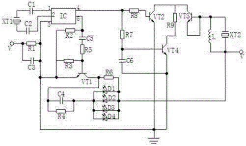
[0011] Such as figure 1 Shown: the first crystal oscillator XT1 of the present invention, the second crystal oscillator XT2, the first capacitor C1, the second capacitor C2, the third capacitor C3, the fourth capacitor C4, the fifth capacitor C5, the sixth capacitor C6, the first resistor R1, The second resistor R2, the third resistor R3, the fourth resistor R4, the fifth resistor R5, the sixth resistor R6, the seventh resistor R7, the eighth resistor R8, the ninth resistor R9, the first infrared diode D1, the second infrared diode D2, the third infrared diode D3, the fourth infrared diode D4, the first triode VT1, the second triode VT2, the third triode VT3, the fourth triode VT4, the signal generating chip IC and the inductor L, The voltage input end is simultaneously connected with the first end of the first resistor R1, the first end of the third capacitor C3, the seco...


PUM


Abstract

The invention discloses a sign pen emission circuit of an infrared electronic white board. The sign pen emission circuit of the infrared electronic white board comprises a first crystal oscillator, a second crystal oscillator, a first capacitor, a second capacitor, a third capacitor, a fourth capacitor, a fifth capacitor, a sixth capacitor, a first resistor, a second resistor, a third resistor, a fourth resistor, a fifth resistor, a sixth resistor, a seventh resistor, an eighth resistor, a ninth resistor, a first infrared diode, a second infrared diode, a third infrared diode, a fourth infrared diode, a first audion, a second audion, a third audion, a fourth audion, a sign generation chip and an inductor. A writing operation is carried out through ultrasonic positioning and an infrared tracking technology, the sign pen emission circuit is strong in emission signs and stable in energy, can accurately write on the electronic white board, can avoid a misoperation brought by that a wrist enters an electronic infrared frame under a condition that the sign pen normally writes, and improves the stability, the sensitivity and the accuracy of electronic writing.

Description

technical field [0001] The invention relates to a signal transmitting circuit, in particular to a signal pen signal transmitting circuit of an infrared electronic whiteboard. Background technique [0002] The classroom is an important position in school education, and the blackboard is an indispensable tool for classroom teaching. It is used to present teaching content and organize teaching activities. Because blackboards are cheap and easy to use, blackboards have spread throughout all schools and classrooms. However, as With the continuous progress of society, the defects of the blackboard have become more and more obvious to us, so multimedia teaching has emerged as the times require. However, the projection teaching method of the large screen also has many shortcomings. The teacher cannot modify the content of the large screen at any time. The large screen The content is relatively fixed and lacks flexibility. Nowadays, interactive electronic whiteboards have appeared. ...

Claims


Application Information

Patent Timeline
Patent Type & Authority Applications(China)
IPC IPC(8): G06F3/0354G06F3/042G06F3/043
Inventor 刘先云
Owner 四川中时代科技股份有限公司
Why Eureka
Try Eureka