

Electronic equipment
An electronic device and technology, applied in the field of information processing, can solve problems such as affecting user experience, poor received signal, and user distress.
- Summary
- Abstract
- Description
- Claims
- Application Information
AI Technical Summary
Problems solved by technology
Method used
Image

Examples
Embodiment 1
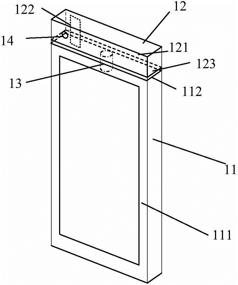
[0037] An embodiment of the present invention provides an electronic device, such as figure 1 As shown, the electronic device has a body part 11, a movable part 12 and a connector 13; wherein,
[0038] The body part 11 and the movable part 12 can change relative positions through the connecting piece 13;
[0039] Described body part 11 comprises first surface 111, and described first surface 111 is provided with display unit; Described movable part 12 comprises second surface 121; The long side of described second surface 121 is equal to the long side of described first surface 111 Short side: the first communication antenna unit 122 is arranged in the movable part 12 .
[0040] Here, the first communication antenna unit may be an antenna used for communication, or may be a GPS or WIFI antenna.
[0041] As the relative position of the movable part and the body part changes, the first communication antenna unit in the movable part can change its direction and receive signals ...
Embodiment 2
[0044] An embodiment of the present invention provides an electronic device, such as figure 1 As shown, the electronic device has a body part 11, a movable part 12 and a connector 13; wherein,
[0045] The body part 11 and the movable part 12 can change relative positions through the connecting piece 13;
[0046] Described body part 11 comprises first surface 111, and described first surface 111 is provided with display unit; Described movable part 12 comprises second surface 121; The long side of described second surface 121 is equal to the long side of described first surface 111 Short side: the first communication antenna unit 122 is arranged in the movable part 12 .
[0047] Here, the first communication antenna unit may be an antenna used for communication, or may be a GPS or WIFI antenna.
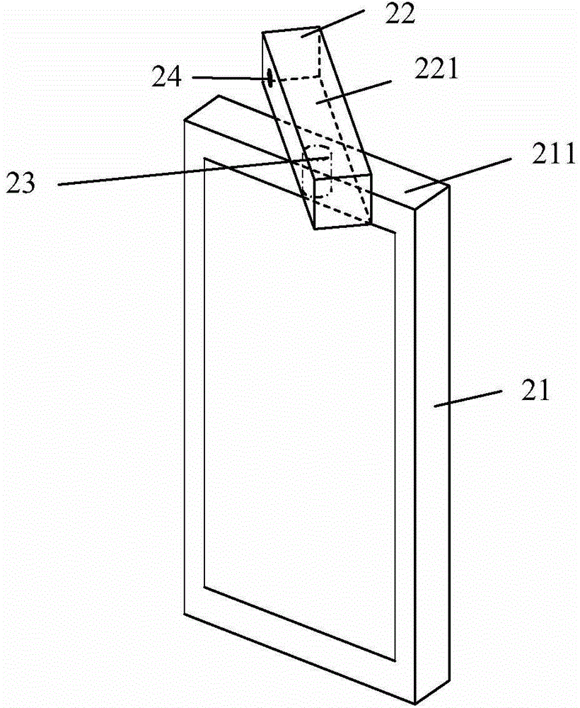
[0048] Further, such as figure 1 As shown, when the movable part 12 and the body part 11 are in the first relative position, the first surface 111 and the second surface 121 are bo...
Embodiment 3
[0055] An embodiment of the present invention provides an electronic device, such as figure 1 As shown, the electronic device has a body part 11, a movable part 12 and a connector 13; wherein,
[0056] The body part 11 and the movable part 12 can change relative positions through the connecting piece 13;
[0057] Described body part 11 comprises first surface 111, and described first surface 111 is provided with display unit; Described movable part 12 comprises second surface 121; The long side of described second surface 121 is equal to the long side of described first surface 111 Short side: the first communication antenna unit 122 is arranged in the movable part 12 .
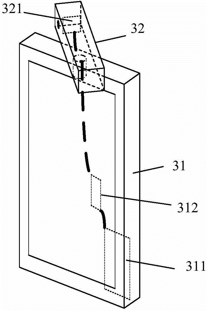
[0058] Further, such as figure 1 As shown, when the movable part 12 and the body part 11 are in the first relative position, the first surface 111 and the second surface 121 are both located in the first plane; at this time, the movable part 12 The first end surface 123 is parallel to the second end surfac...
PUM
 Abstract
Description
Claims
Application Information