Heating arrangement for heating a fluid utilizing a solar panel

A heating device and liquid technology, applied in solar heating systems, machines using solar energy, solar thermal energy, etc., can solve the problems of redundancy, damage, and high cost of heating systems, to promote heat transfer, faster defrosting, and prevent Effects of Part Condensation

Active Publication Date: 2015-05-13
SOLETAER
View PDF5 Cites 0 Cited by
  • Summary
  • Abstract
  • Description
  • Claims
  • Application Information

AI Technical Summary

Problems solved by technology

In a house, water used as tap water needs to be heated to the right temperature and stored in tanks for use when needed, and supplying such heated water through traditional methods is often expensive
[0003] Renewable energy sources such as solar panels can be used to reduce costs, however, in colder climates it is often difficult to meet the year-round energy demand for heating tap water due to the size of the solar panels required and their associated costs
However, solar panels, which are necessary in winter, are not needed in bright summer months, resulting in redundant heating systems and excess energy for heating water
As a result, the liquid in the solar panel is heated to a boil causing damage and the risk of freezing damage in winter
[0004] Some systems are known to solve these problems, however, most of these systems are too expensive and bulky for consumers living in smaller homes
In many houses, air-to-air heat pumps are installed to heat the indoor air, while air-to-water heat pumps are also used to heat tap water and / or water from radiators, etc. They are more expensive and are not used
In addition, for homes where heating systems are already in place, retrofitting heating systems more efficiently is inherently expensive and thus disadvantageous to consumers
[0005] Another problem faced by users of such installations is the need for defrosting in colder climates in order to avoid unacceptable loss of efficiency due to icing on installation components
Defrost usually requires a lot of energy and the unit must not heat the water during the defrost operation causing further losses

Method used


Image

  • Heating arrangement for heating a fluid utilizing a solar panel
  • Heating arrangement for heating a fluid utilizing a solar panel
  • Heating arrangement for heating a fluid utilizing a solar panel

Examples


Embodiment Construction

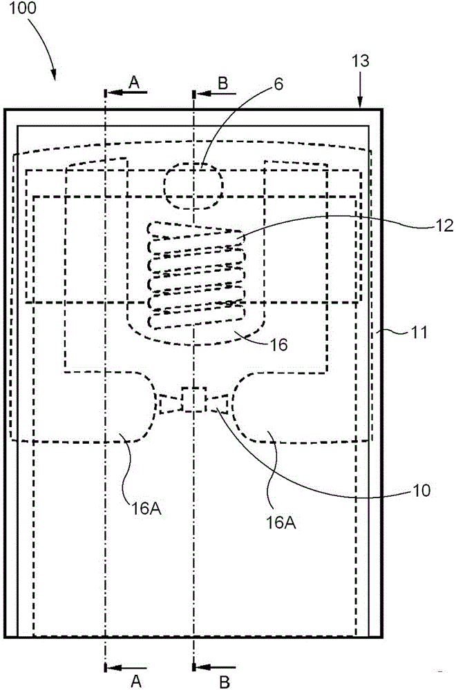
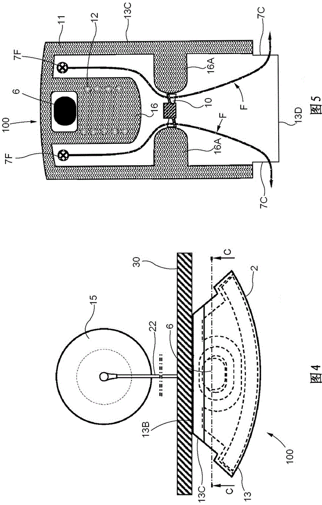
[0024] exist figure 1 , figure 2 and image 3 , schematically illustrates a device 100 according to a preferred embodiment of the present invention. There is a transparent outer wall 2 on the front of the device 100 and a distance t inside the transparent outer wall 2 1 There is a panel 4, preferably, the panel 4 is metal. An inlet flow gap 7 for the flow of air F is formed between the wall 2 and the panel 4 . The top of the transparent outer wall 2 is connected to a housing 13 having a top wall 13A, a rear wall 13B, side walls 13C and a bottom 13D. The distance t between the rear wall 13B and the panel 4 2 (than t 1 Larger) to form a downflow compartment 7D and a space larger than the inlet flow gap 7. The bottom 13D extends horizontally between the rear wall 13B and the panel 4 but not between the panel 4 and the transparent outer wall 2 , forming a downwardly open gap 7A between said transparent outer wall 2 and the panel 4 . The panel 4 extends upwards from the bo...


PUM


Abstract

The present invention relates to a heating arrangement for heating a fluid, comprising a first heat exchanger loop (5), arranged to act on a fluid to be heated, and a second heat exchanger loop (8), arranged to also act on said fluid to be heated, wherein said second heat exchanger loop (8) is connected to a panel (4) that serves as a solar collector and that is arranged to heat at least a part of said second heat exchanger loop (8).

Description

technical field [0001] The invention relates to a heating device for heating a liquid comprising a first heat exchanger circuit arranged to act on the liquid to be heated and a second heat exchanger circuit arranged to also act on said liquid to be heated. Background technique [0002] Various heating devices are known in the field of heating liquids, such as building water. In a house, water used as tap water needs to be heated to a suitable temperature and stored in a tank for use when needed, and supplying such heated water by conventional methods is usually expensive. [0003] To reduce costs, renewable energy sources such as solar panels can be used, however, in colder climates it is often difficult to meet the energy requirements for heating tap water year-round due to the size of the solar panels required and their associated costs. However, solar panels, which are necessary in winter, are not needed in bright summer months, resulting in redundant heating systems and...

Claims


Application Information

Patent Timeline
Patent Type & Authority Applications(China)
IPC IPC(8): F24D11/02F24D17/02F24H4/04F25B27/00F25B30/02
CPCF24H4/04F24D17/02F25B27/005Y02B10/20Y02B10/70F24D11/0221F24D2200/12F24D2200/14Y02A30/272F24S10/00Y02E10/44F24D11/02F24D17/0015F25B27/00
Inventor A·菲耶斯塔德
Owner SOLETAER
Why Eureka
Try Eureka