Flexible supporting mechanism for machining plate workpiece

A flexible support and support column technology, used in metal processing mechanical parts, workpiece clamping devices, metal processing equipment, etc., can solve problems such as workpiece support and positioning, and achieve stable and reliable performance.

Active Publication Date: 2015-05-20
TAIAN HUALU METALFORMING MACHINE TOOL
View PDF7 Cites 33 Cited by
  • Summary
  • Abstract
  • Description
  • Claims
  • Application Information

AI Technical Summary

Problems solved by technology

Utilizing the mechanism designed by the invention can solve the difficult problem of wor

Method used


Image

  • Flexible supporting mechanism for machining plate workpiece
  • Flexible supporting mechanism for machining plate workpiece
  • Flexible supporting mechanism for machining plate workpiece

Examples


Embodiment 1

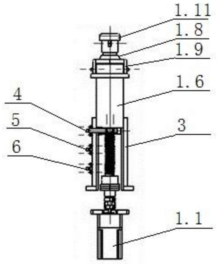
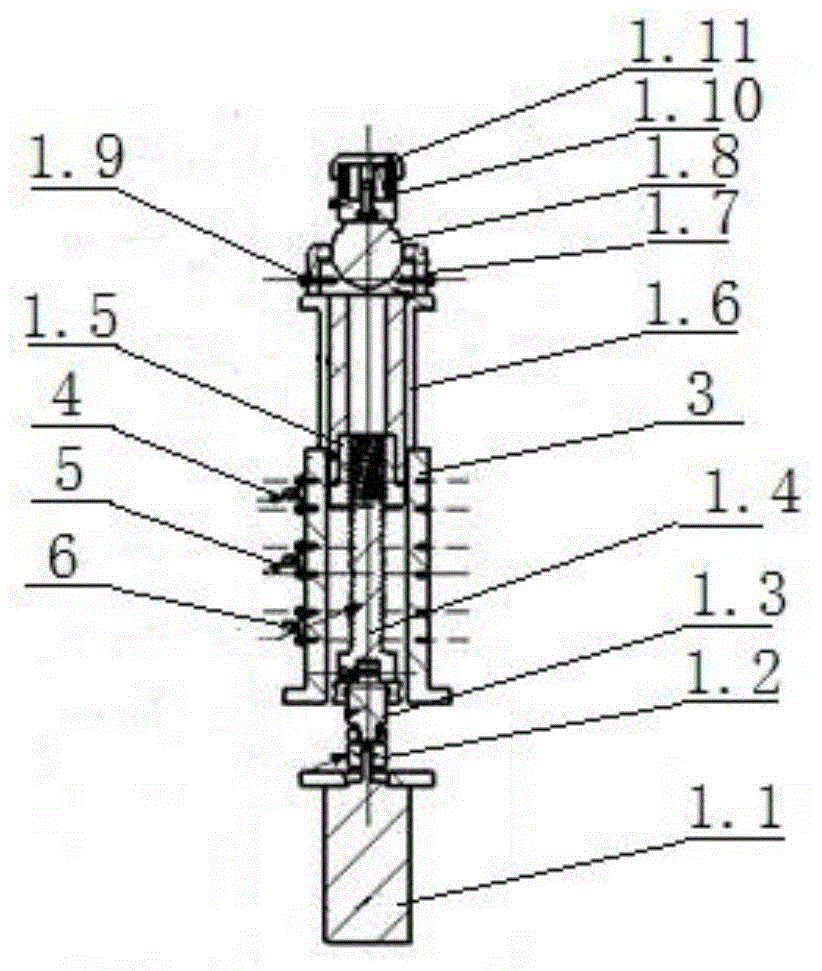
[0019] Embodiment 1: as image 3 As shown, a discrete support column is characterized in that: the shaft of the motor 1.1 is connected to one end of the connecting shaft 1.3 through a coupling 1.2, and the other end of the connecting shaft 1.3 is fixed on the lifting screw 1.4, and the outside of the lifting screw 1.4 has a trapezoidal thread. The nut 1.5 is set on the outside of the lifting screw 1.4, and the inner surface of the lifting nut 1.5 also has trapezoidal threads. The trapezoidal threads on the outside of the lifting screw 1.4 match the trapezoidal threads on the inside of the lifting nut 1.5. The lower end of the lifting sleeve 1.6 is fixed on the lifting nut 1.5. Universal ball joint seat 1.7 is fixed on the upper end of barrel 1.6, universal ball joint 1.8 is installed on universal ball joint seat 1.7, universal ball joint ferrule 1.9 is fixed on the outer side of universal ball joint 1.8, and the upper part of universal ball joint 1.8 is fixed with electromagnet...

Embodiment 2

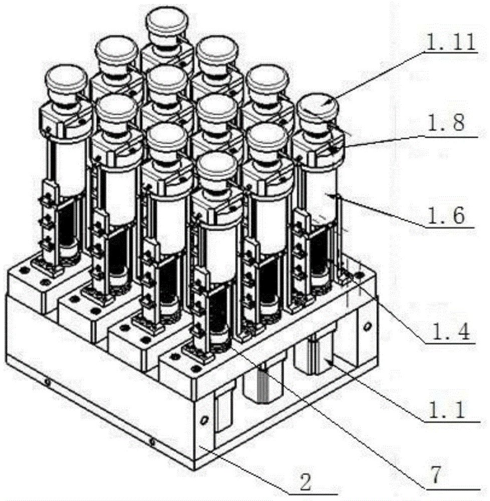
[0020] Embodiment 2: as figure 1 As shown, a flexible support mechanism for processing plate workpieces is characterized in that: the base 2 has two upper and lower layers, the discrete support column 1 passes through the upper layer of the base 2 and is fixed on the lower layer of the base 2, and the motor 1.1 of the discrete support column 1 is fixed On the lower layer of the base 2, the shaft of the motor 1.1 is connected to one end of the connecting shaft 1.3 through a coupling 1.2, the other end of the connecting shaft 1.3 is fixed on the lifting screw 1.4, the connecting shaft 1.3 is set in the thrust ball bearing 7, and the lower end of the thrust ball bearing 7 is placed On the upper layer of the base 2, the upper end of the thrust ball bearing 7 is in contact with the lifting screw 1.4. There is a trapezoidal thread on the outside of the lifting screw 1.4, and the lifting nut 1.5 is set on the outside of the lifting screw 1.4. The thread coincides with the trapezoidal...

Embodiment 3

[0021] Embodiment 3: A flexible support mechanism for processing plate workpieces, characterized in that: the base 2 has two layers, the discrete support column 1 passes through the upper layer of the base 2 and is fixed on the lower layer of the base 2, and the motor 1.1 of the discrete support column 1 Fixed on the lower layer of the base 2, the shaft of the motor 1.1 is connected to one end of the connecting shaft 1.3 through the coupling 1.2, the other end of the connecting shaft 1.3 is fixed on the lifting screw 1.4, the connecting shaft 1.3 is set in the thrust ball bearing 7, and one end of the thrust ball bearing 7 Placed on the upper layer of the base 2, the other end is in contact with the lifting screw 1.4. There is a trapezoidal thread on the outside of the lifting screw 1.4. The lifting nut 1.5 is set on the outside of the lifting screw 1.4. The inner surface of the lifting nut 1.5 also has a trapezoidal thread. The trapezoidal thread on the inner side of the lifti...


PUM


Abstract

The invention relates to the field of machining, in particular to a flexible supporting mechanism for machining a plate workpiece. The flexible supporting mechanism comprises a discrete supporting column and is characterized in that a motor shaft is connected with one end of a connecting shaft through a coupler, the other end of the connecting shaft is fixed onto a lifting screw, a trapezoidal thread is arranged on the outer side of the lifting screw, a lifting nut sleeves the outer side of the lifting screw, a trapezoidal thread is arranged on the inner surface of the lifting nut, the trapezoidal thread on the outer side of the lifting screw is matched with the trapezoidal thread on the inner side of the lifting nut, the lower end of a lifting sleeve is fixed onto the lifting nut, a universal ball joint seat is fixed at the upper end of the lifting sleeve, a universal ball joint is mounted on the universal ball joint seat, a universal ball joint clamp sleeve is fixed on the outer side of the universal ball joint, an electromagnetic sucker seat is fixed on the upper portion of the universal ball joint, an electromagnetic sucker and a complex curved surface plate flexible machining device are mounted on the electromagnetic sucker seat, and the complex curved surface plate flexible machining device is provided with the supporting column. The flexible supporting mechanism has the advantages that relative positions of supporting columns can be randomly adjusted according to plate shapes, the top of each supporting column can spatially and freely swing through the universal ball joint, absorption of the electromagnetic sucker is added, working performances are stable and reliable, and the lifting screw is prevented from sliding by thread self-locking.

Description

technical field [0001] The invention relates to the field of mechanical processing, in particular to a flexible support mechanism for processing plate workpieces. Background technique [0002] At present, there are mainly two types of ship plate processing methods at home and abroad: mechanical stamping method or water and fire bending method. For different processing methods, the plate supporting mechanism is also different. The mechanical stamping method mainly relies on the die to fix the plate workpiece in the die. The water and fire bending method does not have a specific support mechanism, but just fix the plate on the ground. [0003] Aiming at the problem of support and positioning in the current ship plate processing process, the invention designs a flexible support mechanism for processing plate workpieces, which is mainly used for supporting and positioning the plate workpieces in the complex ship plate processing process. Moreover, the invention can also be us...

Claims


Application Information

Patent Timeline
IPC IPC(8): B23Q3/00B25B11/00
CPCB23Q3/00B25B11/00
Inventor 杜如虚刘庆印何凯常欣
Owner TAIAN HUALU METALFORMING MACHINE TOOL
Why Eureka
Try Eureka