A variable flow area suction nozzle for road sweeping vehicles
A technology for road cleaning and circulation area, applied in road cleaning, cleaning methods, construction, etc., can solve the problems of complex product models, unrealistic, narrow range of operating speed, etc., to improve cleaning quality and operating efficiency, increase adaptability Ability to optimize the effect of the flow field
- Summary
- Abstract
- Description
- Claims
- Application Information
AI Technical Summary
Problems solved by technology
Method used
Image
Examples
Embodiment 1
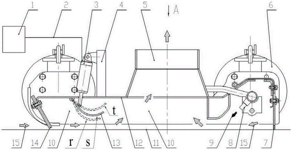
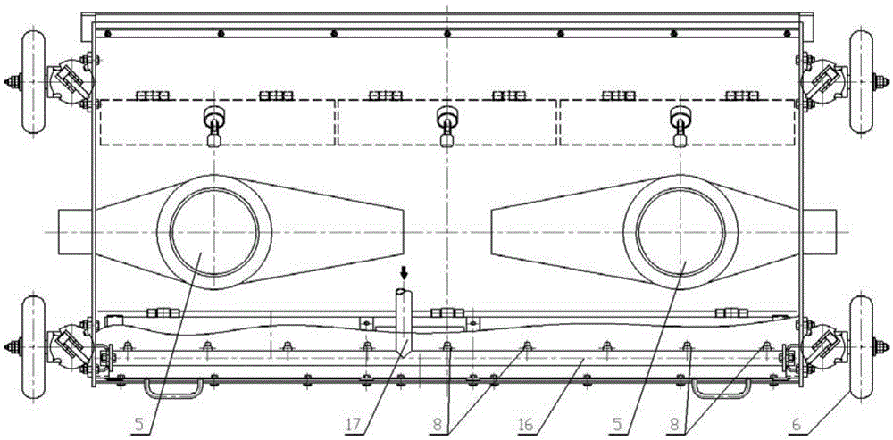
[0066] The variable flow area road sweeper suction nozzle, see figure 1 , figure 2 Its structure includes a nozzle body 12 composed of an upper side panel, a shroud, etc., and the front and rear sides of the nozzle body 12 are respectively provided with a front windshield 14 and a rear windshield 14 with certain flexibility near the ground. The windshield 7 is jointly surrounded by the suction nozzle body 12, the front windshield 14, and the rear windshield 7 to form a suction nozzle inner cavity 10, and the upper side of the suction nozzle body 12 is provided with the suction nozzle inner cavity 10. The conveying pipe of Unicom is provided with casters 6 respectively on both sides. In the inner cavity 10 of the suction nozzle, a high-pressure water pipe 16 is provided between the inlet of the delivery pipe 5 and the rear windshield 7 , and the high-pressure water pipe 16 is provided with a water inlet pipe 17 and a nozzle 8 .
[0067] In the inner cavity 10 of the suction no...
Embodiment 2
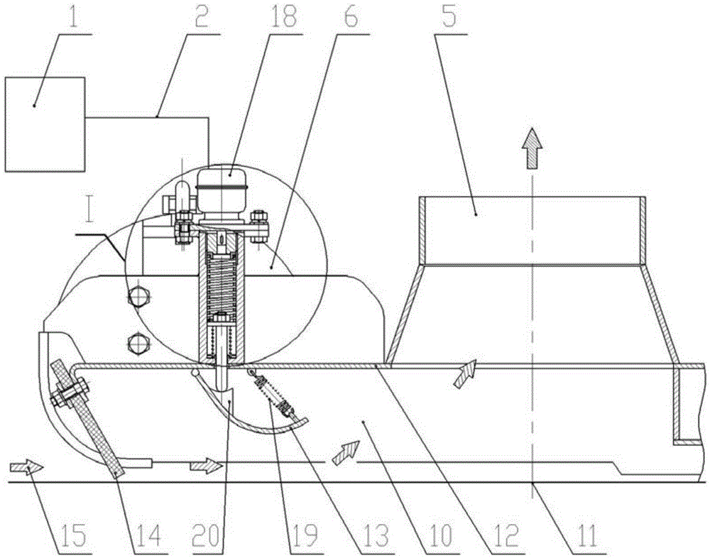
[0077] The variable flow area road sweeper suction nozzle, in image 3 combined on the basis of Figure 4 , the difference between this scheme and embodiment 1 is:
[0078] ①The tongue plate 13 is provided with a support seat 20 with a pit-shaped top surface, and apart from the full hinged relationship between the tongue plate 13 and the nozzle body 12, there is also a joint between the tongue plate 13 and the nozzle body 12. A return tension spring 19 is arranged between the side panels;
[0079] ② Cancel the driving rod 3 and the fixing seat 4 in Embodiment 1, and replace it with a threaded sleeve 22 with internal threads above the upper side plate of the nozzle body 12, and the end of the threaded sleeve 22 is provided with a driver 18 , the threaded sleeve 22 is provided with a threaded block 21 driven by the driver 18 with an external thread, and the internal thread of the threaded sleeve 22 cooperates with the external thread of the threaded block 21 . One end of the ...
Embodiment 3
[0082] The variable flow area road sweeper suction nozzle, in Figure 5 combined on the basis of Figure 6 , Figure 7 , Figure 8 , the difference between this scheme and embodiment 2 is:
[0083] ① Cancel the threaded sleeve 22, driver 18, threaded block 21, threaded sleeve 22, drive spring 23, spring seat 24, return spring 25, push rod 26, and replace it with the upper side panel of the nozzle body 12 A support sleeve 32, the interior of the support sleeve 32 is provided with a lifting sleeve 34 with an internal thread, and the support sleeve 32 and the lifting sleeve 34 are connected by a sliding key 37, and the lifting sleeve 34 is provided with a lifting sleeve with an external thread section. Rotating shaft 31, the inner thread of the lifting sleeve 34 cooperates with the outer thread section of the rotating shaft 31, the top of the supporting sleeve 32 is provided with a positioning cover 30, the lower end of the rotating shaft 31 is provided with a push rod 35, and...
PUM
 Abstract
Description
Claims
Application Information
 - R&D
- Intellectual Property
- Life Sciences
- Materials
- Tech Scout
- Unparalleled Data Quality
- Higher Quality Content
- 60% Fewer Hallucinations
Browse by: Latest US Patents, China's latest patents, Technical Efficacy Thesaurus, Application Domain, Technology Topic, Popular Technical Reports.
© 2025 PatSnap. All rights reserved.Legal|Privacy policy|Modern Slavery Act Transparency Statement|Sitemap|About US| Contact US: help@patsnap.com


