Ultralow-pressure well leakage plugging method

A plugging method and ultra-low pressure technology, applied in chemical instruments and methods, earthwork drilling, wellbore/well components, etc., can solve the problem of cement pipe strings stuck in the wellbore, unable to achieve effective plugging, and cement slurry Leakage and other problems, to achieve the effect of guaranteed construction quality, improved pressure bearing capacity, and high cost

Active Publication Date: 2015-05-20
PETROCHINA CO LTD
View PDF7 Cites 29 Cited by
  • Summary
  • Abstract
  • Description
  • Claims
  • Application Information

AI Technical Summary

Problems solved by technology

However, there are some defects in the use of this method, especially when plugging the above-mentioned ultra-low pressure wells, it is easy to cause: (1) a large amount of working fluid is lost during construction, polluting the reservoir; (2) the cement slurry is easy to be plugged The target layer loses water instantaneously due to the action of gravity, causing the squeezed cement pipe string to be solidified in the wellbore (called "flag sticking"), or causing the pipe string to be filled with solidified cement plugs (called "sausage filling") ) and other high-risk complex engineering accidents; (3) The cement slurry is completely lost in the leaky layer, and the purpose of effective plugging cannot be achieved; (4) This method has high risk, high cost, long operation period, and low pressure

Method used


Image

  • Ultralow-pressure well leakage plugging method
  • Ultralow-pressure well leakage plugging method
  • Ultralow-pressure well leakage plugging method

Examples


Embodiment 1

[0023] Embodiment 1: as figure 1 , figure 2 As shown, a plugging method for ultra-low pressure wells in oilfields can effectively reduce the large loss of working fluid, reduce the incidence of engineering accidents, and have a high plugging success rate.

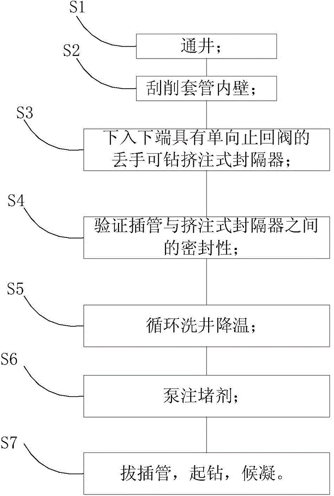
[0024] The ultra-low pressure well plugging method includes the following steps:

[0025] a. After selecting a perforated well section as the entrance of cement slurry, set a squeeze packer in the upper casing of the perforated well section. return valve;

[0026] b. Lower the squeeze string, insert the cannula at the lower end of the squeeze string into the socket of the packer, so as to seal the gap between the string and the squeeze packer, and prevent the plugging agent from returning to the squeeze during plugging construction. Injection packer caused engineering accidents;

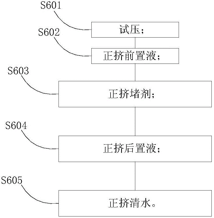
[0027] c. First pump the gel spacer fluid into the squeeze string, then pump the cement slurry, and finally pump the gel spacer fluid, squee...


PUM

PropertyMeasurementUnit
viscosityaaaaaaaaaa
viscosityaaaaaaaaaa

Abstract

The invention provides an ultralow-pressure well leakage plugging method and belongs to the technical field of oil field well leakage plugging. According to the method, after a certain perforation well section is selected as an inlet of cement slurry, a squeezing packer is arranged in a casing pipe of the upper portion of the perforation well section in a setting mode, and a drillable one-way check valve is arranged under the squeezing packer; a squeezing pipe column is fed, an insertion pipe at the lower end of the squeezing pipe column is inserted into a socket of the packer so that the pipe column and the squeezing packer can be sealed, and the situation that due to the fact that plugging agents return to the portion above the squeezing packer in the plugging construction process, engineering accidents are caused can be prevented; gel spacer fluid is pumped into the squeezing pipe column, then the cement slurry is pumped, finally the gel spacer fluid is pumped, positive pressure squeezing is carried out, and therefore the gel spacer fluid and the cement slurry enter an oil-water layer or a channeling groove part to be sealed through the perforation well section serving as the inlet; pumping is stopped, the insertion pipe is pulled out, the one-way check valve is automatically closed, flow return is stopped, the pipe column is lifted to finish the operation of plugging the oil-water layer, kill fluid is poured, and a well is closed to wait on cement setting. The method has the advantages that site adaptation and leakage plugging strength are high, and leakage of the ultralow-pressure well can be plugged.

Description

technical field [0001] The invention relates to an ultra-low pressure well plugging method, which belongs to the technical field of oil well plugging in oil fields. Background technique [0002] In the middle and later stages of development, the carbonate rock formation in the oilfield gradually reduces formation pressure and has relatively developed caves and fractures. After frequent acidification and acid fracturing, ultra-low pressure caverns and fractures are formed. Circulation cannot be established, and the dynamic fluid level is below 2000 meters. This requires plugging the lost zone of the oil well. [0003] Existing oil well plugging methods usually use bare pipe strings to repeatedly squeeze cement to plug the lost zone. However, there are some defects in the use of this method, especially when plugging the above-mentioned ultra-low pressure wells, it is easy to cause: (1) a large amount of working fluid is lost during construction, polluting the reservoir; (2) ...

Claims


Application Information

Patent Timeline
Patent Type & Authority Applications(China)
IPC IPC(8): E21B33/13C09K8/40
CPCC09K8/40E21B33/13
Inventor 李强欧如学钟家维宋中华单全生杨国洪石元龙陆爱华张超赵丽宏田俊艳
Owner PETROCHINA CO LTD
Why Eureka
Try Eureka