
Mining environment-reconstructing mobile pumping filling artificial pillar shrinkage mining method

An artificial ore pillar, mobile technology, applied in surface mining, underground mining, special mining, etc., can solve the problems of high mining cost, high ore loss rate, roof falling in goaf, etc., to solve the problem of high mining loss rate , the effect of improving resource recovery rate and reducing mining cost

Active Publication Date: 2015-05-20
CENT SOUTH UNIV +2
View PDF4 Cites 13 Cited by
  • Summary
  • Abstract
  • Description
  • Claims
  • Application Information

AI Technical Summary

Problems solved by technology

[0002] For steeply inclined thin ore bodies, the shallow hole ore retention method is often used in the traditional technology for mining. The ore body is divided into ore rooms and ore pillars. The thickness is small and scattered, it is difficult to build a filling pipeline system, and the filling mining method cannot be used. The ore pillars are generally permanent ore pillars and cannot be recovered
Therefore, this process has the disadvantages of high ore loss rate and poor safety.
Especially when the ore body is not stable, the ore pillar is prone to damage and collapse, which will lead to the roof caving of the goaf and cause ground pressure disasters
If the filling mining method is adopted, it will bring disadvantages such as high investment in filling system construction, complicated filling process, and high mining cost, which will reduce the economic benefits of the mine.

Method used


Image

  • Mining environment-reconstructing mobile pumping filling artificial pillar shrinkage mining method
  • Mining environment-reconstructing mobile pumping filling artificial pillar shrinkage mining method
  • Mining environment-reconstructing mobile pumping filling artificial pillar shrinkage mining method

Examples


Embodiment Construction

[0013] The present invention will be further described below in conjunction with the accompanying drawings and embodiments.

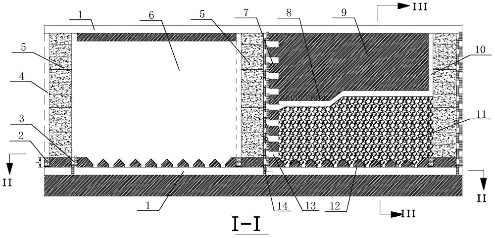
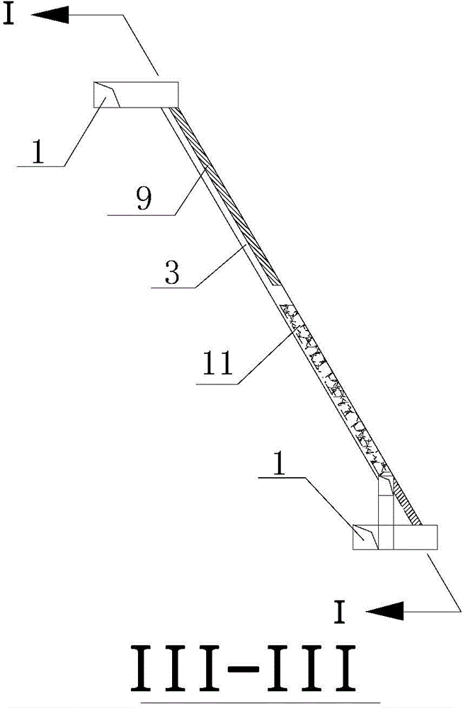
[0014] see figure 1 , figure 2 and image 3 , in the picture: 1. Middle transportation roadway, 2. Artificial false bottom, 3. Pedestrian inclined shaft, 4. Slide shaft, 5. Artificial pillar, 6. Goaf, 7. Reserved pillar, 8. Blasting hole, 9. Unmined ore body, 10. Stope return air shaft, 11. Caving ore, 12. Funnel, 13. Pedestrian contact roadway, 14. Pedestrian ladder, when mining inclined or steeply inclined thin ore body without filling system, according to mining The ore body is divided into ore houses and pillars along the strike direction. First, the upward layered filling mining technology is used to mine the ore pillars, and the mobile pumping filling system is used for layered filling operations. Inclined shafts and slide shafts are used to reconstruct the mining environment; after the pillars are mined and filled to form artificial pillars, ...


PUM


Abstract

The invention discloses a mining environment-reconstructing mobile pumping filling artificial pillar shrinkage mining method which comprises the following steps: dividing an ore body into a pillar and a chamber; firstly mining the pillar by utilizing a layered filling mining process, filling by adopting a mobile pumping filling system to form an artificial pillar, and reserving a pedestrian and equipment channel for mining environment reconstruction; then stoping the chamber by adopting a shrinkage mining process, reserving the pillar on one side of the chamber, and reserving no pillar on the other side of the chamber; by utilizing a jack shaft as a stope return air shaft, recovering the reserved pillar for one time after the chamber is stoped, and supporting a worked-out section through the artificial pillar without treating the worked-out section so as to realize the purpose of safe mining of a steep-inclined thin ore body. The mining environment-reconstructing mobile pumping filling artificial pillar shrinkage mining method disclosed by the invention is especially suitable for an underground metal mine filling-free system and the mining of a high-grade inclined or steep-inclined thin ore body with a more steady top plate surrounding rock and has the characteristics of low ore loss rate, no need of filling system construction, simple process, safety in operation and few needed filling material.

Description

technical field [0001] The invention relates to an underground metal ore retention mining method, in particular to a mining environment reconstruction mobile pumping filling artificial ore pillar retention mining method, which is suitable for underground mines without a filling system and with relatively stable roof surrounding rocks. Mining of grade inclined or sharply inclined thin ore bodies. Background technique [0002] For steeply inclined thin ore bodies, the shallow hole ore retention method is often used in the traditional technology for mining. The ore body is divided into ore rooms and ore pillars. The thickness is small and scattered, it is difficult to build a filling pipeline system, and the filling mining method cannot be used. The ore pillars are generally permanent ore pillars and cannot be recovered. Therefore, this process has the disadvantages of high ore loss rate and poor safety. Especially when the ore body is not stable, the ore pillars are prone to...

Claims


Application Information

Patent Timeline
IPC IPC(8): E21C41/22
CPCE21C41/22
Inventor 李杰林邓红卫周科平王敏高如高袁梅芳刘伟强彭涛陈研文
Owner CENT SOUTH UNIV
Learn More