
Drive and control circuit for fast solenoid valve

A technology for driving control circuits and solenoid valves, applied in the direction of valve operation/release devices, valve details, valve devices, etc., can solve problems such as unsatisfactory control accuracy and low stability, and achieve improved response speed, control accuracy, and power The effect of reducing power consumption and reducing friction hysteresis

Active Publication Date: 2015-05-20
AVIC NO 631 RES INST
View PDF7 Cites 9 Cited by
  • Summary
  • Abstract
  • Description
  • Claims
  • Application Information

AI Technical Summary

Problems solved by technology

[0004] The present invention proposes a drive control circuit for a fast solenoid valve to solve the problems of unsatisfactory control accuracy and low stability in the prior art

Method used


Image

  • Drive and control circuit for fast solenoid valve
  • Drive and control circuit for fast solenoid valve
  • Drive and control circuit for fast solenoid valve

Examples


Embodiment Construction

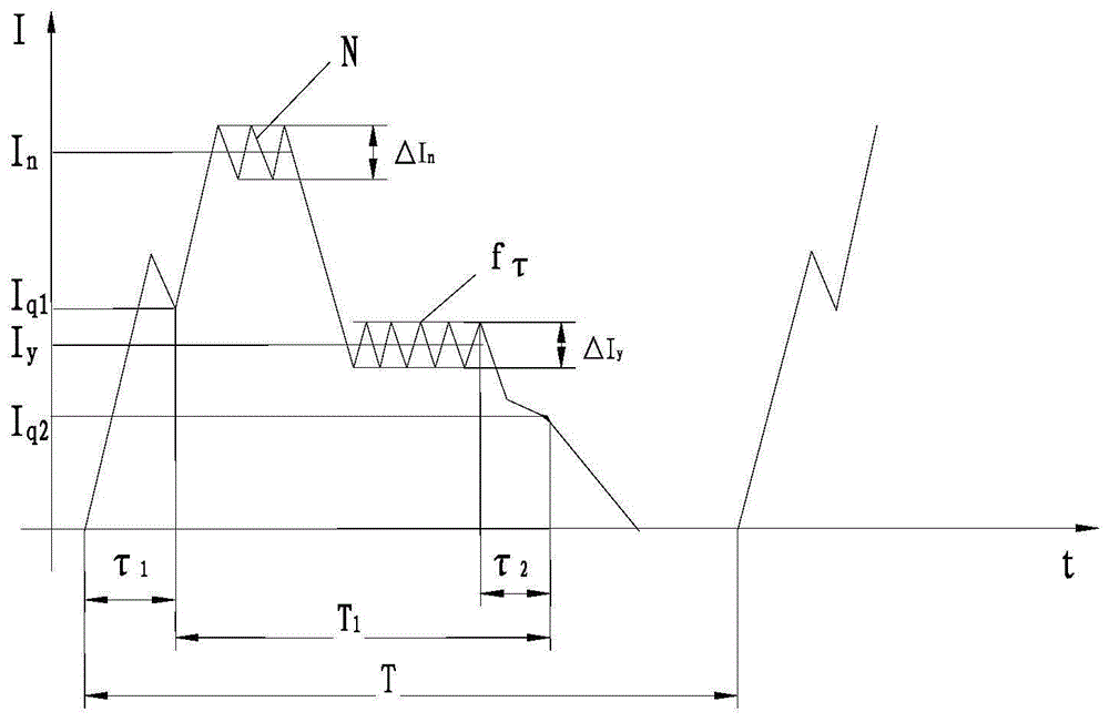
[0042] Combined with the test of this circuit in an electronic controller project, the implementation mode and use effect of this circuit will be explained in detail.

[0043] The RST1 and RST2 signals that control the general-purpose timer D1 are generated by the event manager of the DSP. The two control signals RST1, RST2 and the final pulse waveform are as follows: Figure 6 As shown, 10ms to 40ms in the figure corresponds to a complete pulse cycle.

[0044] RST1 and RST2 are respectively controlled by peripheral function pins PWM1 and PWM3 belonging to the DSP event manager. These two control signals are generated by comparison unit 1 and comparison unit 2, and use general-purpose timer 1 together. 10-40ms is general-purpose timer 1 A counting period of the counting cycle, the comparison match of comparison unit 1 is generated at 20ms, and RST1 is flipped; the comparison match of comparison unit 2 is generated at 30ms, and RST2 is flipped; the period match of general-purpo...


PUM


Abstract

The invention provides a drive and control circuit for a fast solenoid valve. The drive and control circuit has the advantages that accuracy and stability are high, and control signals are simple. The drive and control circuit adjusts the intensity or the duration time of a strong shock current and a holding current according to the inherent characteristic of the solenoid valve and mainly comprises an output circuit and a feedback circuit. Two general timers are arranged for control over the strong shock current and the holding current respectively in the output circuit, an output signal OUT1 and an output signal OUT2 can be generated, when any signal is a high-level signal, a transistor V1 or V2 is switched on, then V3 is switched on through an MOSFET, PWM-OUT+ outputs +28V, and the solenoid valve is driven to work. The feedback circuit mainly comprises a difference operational amplifying circuit and a bleeder circuit, and the negative end PWM-OUT- of the solenoid valve is connected into a sampling resistor in the feedback circuit.

Description

technical field [0001] The invention relates to a driving control circuit of a fast electromagnetic valve. Background technique [0002] The fast solenoid valve is an executive part of the engine fuel adjustment system, which can be widely used in aviation, ships, automobiles and other fields. By controlling the regular opening and closing of the fast solenoid valve, the fuel flow can be adjusted to control the engine. change in rotational speed. [0003] Since the fast solenoid valve came out in the 1970s, many manufacturers and companies at home and abroad have studied its structure and control methods. The research on fast solenoid valves in my country began in the late 1980s. The fast solenoid valve drive circuit is mainly composed of discrete components. In recent years, some fast solenoid valve drive circuits realized by application-specific integrated circuits have also emerged. Some drive control circuits control the opening and closing of the solenoid valve by con...

Claims


Application Information

Patent Timeline
Patent Type & Authority Applications(China)
IPC IPC(8): F16K31/06
CPCF16K31/06
Inventor 郝建邢金富于正同
Owner AVIC NO 631 RES INST
Learn More