Backlight module

A backlight module and optical technology, applied in the field of backlight modules, can solve problems such as unfavorable thin design and backlight module thickness

Inactive Publication Date: 2015-05-20
FUTAIHUA PRECISION ELECTRONICS ZHENGZHOU +1
View PDF8 Cites 10 Cited by
  • Summary
  • Abstract
  • Description
  • Claims
  • Application Information

AI Technical Summary

Problems solved by technology

Such a backlight module will be relative...

Method used


Image

  • Backlight module
  • Backlight module
  • Backlight module

Examples


Embodiment Construction

[0016] The backlight module provided by the present invention will be further described in detail below with reference to the drawings and embodiments.

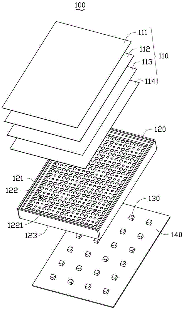
[0017] see figure 1 , the backlight module 100 provided in Embodiment 1 of the present invention is arranged below the liquid crystal panel (not shown in the figure). A plurality of LED light sources 130.

[0018] The optical film set 110 includes a plurality of optical sheets. Preferably, the plurality of optical sheets are a diffusion sheet 111 , a prism sheet 112 , a prism sheet 113 and a diffusion sheet 114 that are stacked.

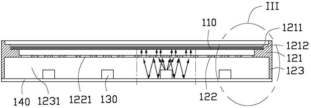
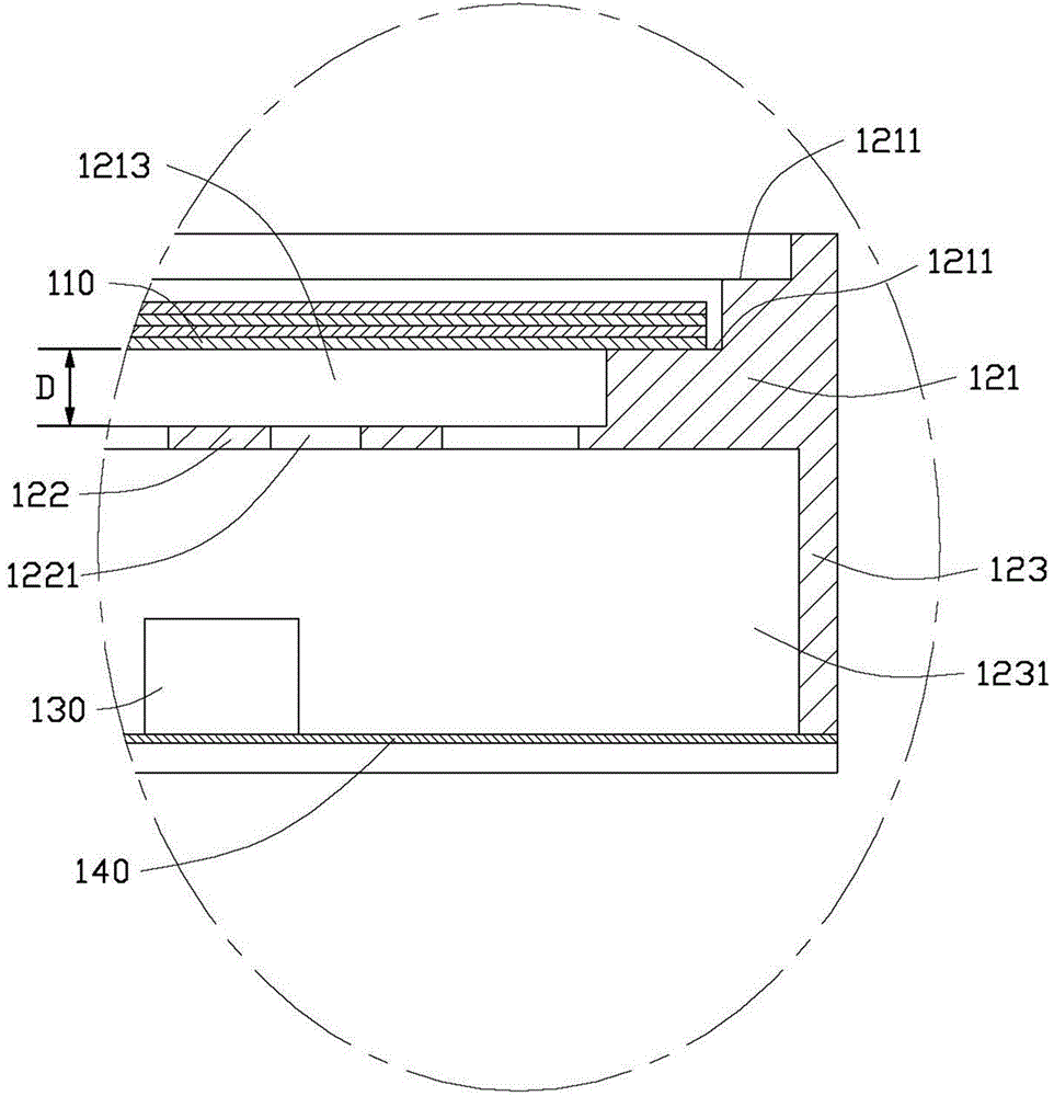
[0019] The reflective frame 120 is made of a plastic material and integrally formed. The reflective frame body 120 includes an upper frame 121 , a reflective plate 122 and a lower frame 123 . Wherein the reflective plate 122 is located at the central portion of the reflective frame 120 .

[0020] Please also see figure 2 and image 3 The upper frame 121 is a rectangular frame with an opening...


PUM


Abstract

A backlight module includes an optical film, a light source panel, a number of light sources mounted on the light source panel, and a reflective frame positioned between the optical film and the light source panel. The reflective frame includes an upper frame, a lower frame, and a reflective plate positioned between the upper frame and the lower frame. The upper frame includes a receiving portion for receiving the optical film, the lower frame is connected with the light source panel, and the reflective plate defines a number of through holes. The reflective plate, the lower frame, and the light source panel cooperatively define a closed chamber.

Description

technical field [0001] The invention relates to a backlight module, in particular to a direct type backlight module. Background technique [0002] Since the liquid crystal panel of the liquid crystal display device cannot emit light, a backlight module needs to provide a light source to realize image display on the liquid crystal panel. However, with the continuous and rapid development of liquid crystal display devices, the backlight modules used in liquid crystal display devices need to be thinned more and more. [0003] Traditionally, people use an edge-lit backlight module to solve the problem of thinning the backlight module. However, the light source of the edge-lit backlight module can only be installed on the side of the light guide plate, so the number of light sources is limited. At the same time, because the edge-lit backlight module uses a light guide plate, there is still a certain amount of absorption loss in the process of light transmission, so the edge-lit ...

Claims


Application Information

Patent Timeline
IPC IPC(8): F21S8/00F21V13/04F21Y101/02
CPCG02F1/133605G02F1/133603G02F1/133608G02F1/133611
Inventor 章绍汉
Owner FUTAIHUA PRECISION ELECTRONICS ZHENGZHOU
Why Eureka
Try Eureka