Defrosting control method for air conditioner

A control method and air conditioner technology, applied in heating and ventilation control systems, refrigerators, heating methods, etc., to avoid overheating and failure, speed up defrosting, and facilitate handling and installation

Active Publication Date: 2015-05-20
GREE ELECTRIC APPLIANCES INC
View PDF5 Cites 23 Cited by
  • Summary
  • Abstract
  • Description
  • Claims
  • Application Information

AI Technical Summary

Problems solved by technology

[0008] The technical problem to be solved by the present invention is to provide a defrosting control method for an air conditioner, which solves the problem that th

Method used


Image

  • Defrosting control method for air conditioner
  • Defrosting control method for air conditioner
  • Defrosting control method for air conditioner

Examples


Embodiment 1

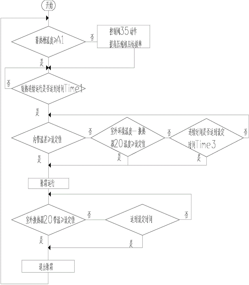
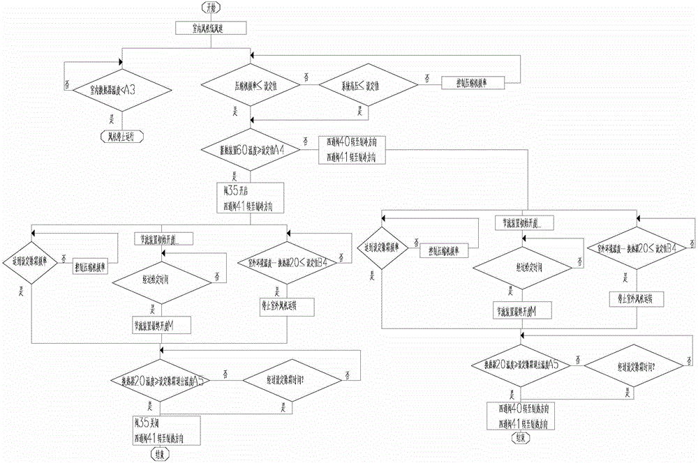
[0041] In order to solve the problems of the prior art, the present invention proposes an air conditioner defrosting control method, such as figure 1 , 2 , 5. In this embodiment, the multi-way control valve is the first four-way valve 40 .

[0042] The air conditioner includes: a compressor 01, a first four-way valve 40, an indoor heat exchanger 10, a throttling device 30, an outdoor heat exchanger 20 and refrigerant pipelines, the compressor 01, the first four-way valve 40 , the indoor heat exchanger 10, the throttling device 30 and the outdoor heat exchanger 20 are connected through refrigerant pipes; the refrigerant pipes include: a first refrigerant pipe 201, a second refrigerant pipe 202, a third refrigerant pipe 203, a fourth refrigerant pipe 204, The fifth refrigerant pipe 205, the sixth refrigerant pipe 206, the seventh refrigerant pipe 207, the eighth refrigerant pipe 208, the ninth refrigerant pipe 209 and the tenth refrigerant pipe 210; the air conditioner also inc...

Embodiment 2

[0075] In this example, if Figure 6 , the multi-way control valve is a three-way valve 50. The air conditioner includes: a compressor 01, a second four-way valve 41, an indoor heat exchanger 10, a throttling device 30, an outdoor heat exchanger 20 and refrigerant pipelines, the compressor 01, the second four-way valve 41 , the indoor heat exchanger 10, the throttling device 30 and the outdoor heat exchanger 20 are connected through refrigerant pipes; the refrigerant pipes include: a first refrigerant pipe 201, a second refrigerant pipe 202, a third refrigerant pipe 203, a fifth refrigerant pipe 205, The sixth refrigerant pipe 206, the seventh refrigerant pipe 207, the eighth refrigerant pipe 208, the ninth refrigerant pipe 209 and the tenth refrigerant pipe 210; the air conditioner also includes: a three-way valve 50, a solenoid valve 35 and a heat storage device 60; the heat storage device 60 is connected in series with the solenoid valve 35, the first connection point B of...


PUM


Abstract

The invention provides a defrosting control method for an air conditioner. The air conditioner comprises a compressor, a first four-way valve, an indoor heat exchanger, a throttling device, an outdoor heat exchanger, a refrigerant pipeline, a second four-way valve, an electromagnetic valve and a heat storage device. When the air conditioner is in heating operation, the first four-way valve and the second four-way valve are both converted into a heating mode, a heat storage mode for the heat storage device is controlled to be started and stopped by controlling the on-off state of the electromagnetic valve, and heat stored by the heat storage device is used for achieving a heat source provided when heating and defrosting are simultaneously conducted. When the air conditioner is in defrosting operation, the first four-way valve is kept in the heating mode, the second four-way valve is converted into a refrigerating mode, the electromagnetic valve is opened, refrigerant gas sprayed by the compressor is divided into two branches, the refrigerant gas exhausted by the compressor simultaneously flows to the indoor heat exchanger and the outdoor heat exchanger, in the defrosting process, refrigerant simultaneously flows to the indoor heat exchanger and the outdoor heat exchanger, certain heat exists on the indoor side, cold radiation is not generated, and user comfort is greatly improved.

Description

technical field [0001] The invention relates to the technical field of air conditioner control methods, in particular to an air conditioner defrosting control method. Background technique [0002] During the heating operation of ordinary heat pump air conditioners, the temperature of the outdoor heat exchanger is lower than the freezing temperature of water, and frost will form. The frost layer increases the thermal resistance, reduces the total heat transfer coefficient of the heat exchanger, and weakens the heating effect of the system during heating. When the outdoor heat exchanger is frosted, the heating mode is switched to the cooling mode by switching the four-way valve for defrosting. In this mode of defrosting, although the indoor fan stops running, the indoor heat exchanger is in a low-temperature state, and there is a problem that the indoor heat exchanger releases cold air into the room, resulting in large fluctuations in the indoor temperature, which affects use...

Claims


Application Information

Patent Timeline
IPC IPC(8): F24F11/00F25B47/00
CPCF24F11/30F24F11/42
Inventor 郭瑞安周中华韩雷陈军宇李潇李俊峰吴会丽
Owner GREE ELECTRIC APPLIANCES INC
Why Eureka
Try Eureka