
Method for automatically calibrating scanning type infrared temperature measuring system deviating from preset monitoring point

A technology of infrared temperature measurement and calibration method, which is applied in the direction of measuring devices, radiation pyrometry, optical radiation measurement, etc., can solve the problems of point thermometer deviation and temperature measurement accuracy drop, so as to avoid the consumption of manpower and material resources and improve Efficiency and accuracy, solving the effect of deviation from preset monitoring points

Active Publication Date: 2015-05-20
SHANGHAI UNIVERSITY OF ELECTRIC POWER
View PDF4 Cites 0 Cited by
  • Summary
  • Abstract
  • Description
  • Claims
  • Application Information

AI Technical Summary

Problems solved by technology

[0003] The invention aims at the problem that the point thermometer deviates from the preset monitoring point caused by the mechanical deformation of the pan platform after the scanning infrared temperature measurement system has been running for a long time, and the temperature measurement accuracy drops, and proposes a scanning infrared temperature measurement system that deviates from the preset monitoring point. The self-calibration method of setting monitoring points, using the infrared point thermometer to reflect the characteristics of the temperature of the key points on the target surface, makes the scanning pan / tilt move the minimum distance of the specified path, and the infrared temperature measuring device will measure the temperature of the corresponding point in a small range near the monitoring point temperature

Method used


Image

  • Method for automatically calibrating scanning type infrared temperature measuring system deviating from preset monitoring point
  • Method for automatically calibrating scanning type infrared temperature measuring system deviating from preset monitoring point
  • Method for automatically calibrating scanning type infrared temperature measuring system deviating from preset monitoring point

Examples


Embodiment Construction

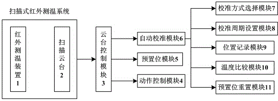
[0019] Such as figure 1 The structural block diagram of the scanning infrared temperature measurement system is shown, and the scanning infrared temperature measurement system is composed of two parts: an infrared temperature measurement device 1 and a scanning cloud platform 2 . The pan-tilt control module 3 is composed of a motion control module 4 , a preset position module 5 and an autonomous calibration module 6 . Among them, the autonomous calibration module 6 is composed of a calibration mode selection module 7 , a calibration cycle setting module 8 , a temperature comparison module 9 , a position recording module 10 , and a preset position reset module 11 .

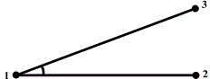
[0020] After the gimbal runs for a long time, the mechanical deformation of the fixed end (such as thermal expansion and contraction) will cause a short-distance and small-angle deviation between the gimbal and the preset position. However, due to factors such as the insulation conditions of electrical equipment, ...


PUM


Abstract

The invention relates to a method for automatically calibrating a scanning type infrared temperature measuring system deviating from a preset monitoring point. The method comprises the following steps of utilizing an infrared point temperature instrument to reflect the characteristic of the temperature of a key point of a target surface, enabling a scanning PTZ (pan / tilt / zoom) to move with minimum distance along a specified path, and enabling the infrared temperature measuring device to measure the temperature of a corresponding point in a small area near the monitoring point; after comparing, determining the displacement point of the PTZ corresponding to the highest temperature, moving the PTZ to the point, and resetting the preset position, so as to automatically calibrating the scanning type infrared temperature measuring system deviating from the preset monitoring point. The method has the advantages that the additional arrangement of other hardware equipment is avoided, the self function extension of the system is utilized, and the monitoring point is calibrated; compared with the traditional manual calibrating method, the consumption of labor and material is avoided, the offset of the PTZ can be timely calibrated, the calibration efficiency and accuracy are improved, and the problem of the infrared temperature measuring system deviating from the preset monitoring point caused by the mechanical deformation of the PTZ in the scanning type infrared temperature measuring system is solved.

Description

technical field [0001] The invention relates to an infrared temperature measurement monitoring point calibration method, in particular to an autonomous calibration method for a scanning infrared temperature measurement system deviated from a preset monitoring point. Background technique [0002] At present, infrared temperature measurement technology is widely used in power equipment condition monitoring. Since handheld infrared temperature measurement equipment consumes manpower and material resources, and is limited by insulation conditions, online infrared temperature measurement systems have been widely developed. In particular, the scanning infrared temperature measurement system combined with the infrared point thermometer and the scanning pan / tilt can expand the measurement range of the infrared point thermometer through periodic scanning and monitoring, so that one point thermometer can play the role of multiple point thermometers. function, greatly reducing the sys...

Claims


Application Information

Patent Timeline
Patent Type & Authority Applications(China)
IPC IPC(8): G01J5/00G01J5/52
Inventor 崔昊杨王超群刘璨王佳林李祥皮凯云许永鹏曾俊冬唐忠
Owner SHANGHAI UNIVERSITY OF ELECTRIC POWER
Learn More