
Test system for feeder automation system

A feeder automation and testing system technology, applied in the field of feeder automation, can solve problems such as heavy burdens and difficulties, and achieve the effect of reducing burdens and solving signal isolation problems

Inactive Publication Date: 2018-02-13
SHANGHAI WISCOM SUNEST ELECTRIC POWER TECH +2
View PDF11 Cites 0 Cited by
  • Summary
  • Abstract
  • Description
  • Claims
  • Application Information

AI Technical Summary

Problems solved by technology

[0004] It is difficult to achieve the isolation of so many signals
At the same time, the signal calculation of so many channels is performed on one MCU, and the burden is too heavy.

Method used


Image

  • Test system for feeder automation system
  • Test system for feeder automation system

Examples


Embodiment Construction

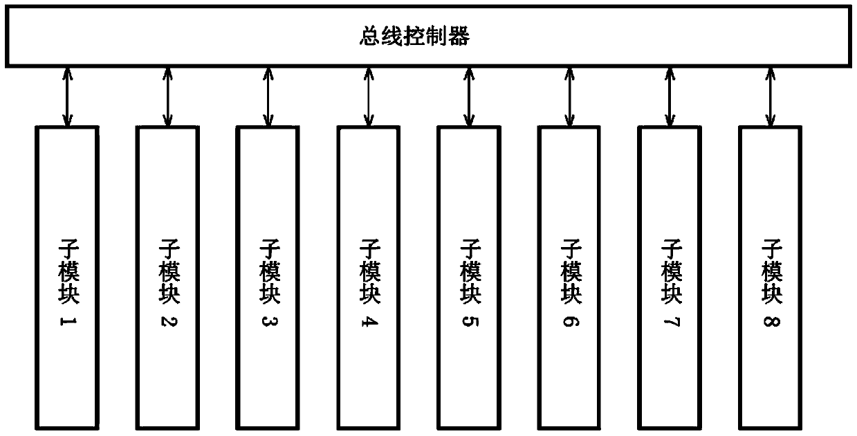
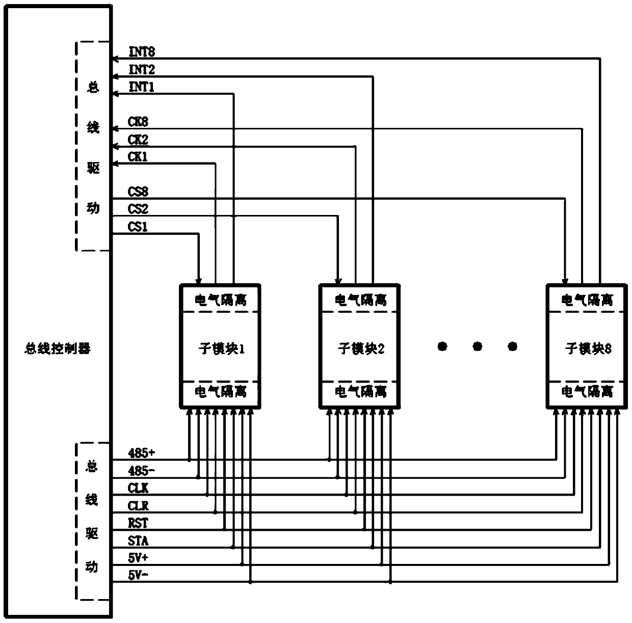
[0029] The following will combine figure 1 and figure 2 The test system of the feeder automation system provided by the present invention is described in detail, which is an optional embodiment of the present invention, and it can be considered that those skilled in the art can modify it within the scope of not changing the spirit and content of the present invention and polish.

[0030] This embodiment provides a test system for a feeder automation system, including several sub-modules and a bus controller; in this embodiment, the number of the sub-modules is eight; each of the sub-modules is configured with a sub-module MCU, The bus controller can be configured with a main MCU;

[0031] The communication signal transmission is realized between the bus controller and each of the sub-modules through the first type of connection line;

[0032] The transmission of control signals between the bus controller and each of the sub-modules is realized through the second type of co...


PUM


Abstract

The invention provides a testing system of a feeder line automatic system. The testing system comprises a plurality of sub-modules and a bus controller, wherein the transmission of a communication signal is realized between the bus controller and each sub-module through a first type of connecting line, the transmission of a control signal is realized between the bus controller and each sub-module through a second type of connecting line, and each sub-module is at least used for responding to the communication signal transmitted by the first type of connecting line, and generating and outputting at least one of an alternating current signal for one path of testing and an alternating current voltage signal for one path of testing according to the communication signal; each sub-module is at least used for responding to the control signal transmitted by the second type of connecting line, and performing running and state feedback according to the control signal.

Description

technical field [0001] The invention relates to the field of feeder automation, in particular to a test system of a feeder automation system. Background technique [0002] In the power system, the power companies all over the world generally use the FA (Feeder Automation) system, that is, the feeder automation system. When a fault occurs at a certain point in the distribution network, it will cause power outages in the same power supply area, and in severe cases, it will lead to large-scale power outages. At this time, the FA system should remove the faulty area as soon as possible, and then restore power to the non-faulty area. [0003] Before the FA system is actually put into application, various functional tests must be carried out. The test equipment is required to independently output 8-channel AC current signal and 8-channel AC voltage signal. It is required that the amplitude and phase of these signals can be independently controlled and electrically isolated from ...

Claims


Application Information

Patent Timeline
Patent Type & Authority Patents(China)
IPC IPC(8): G01R31/00
Inventor 张磐范志杰吴攀王蔚凌万水
Owner SHANGHAI WISCOM SUNEST ELECTRIC POWER TECH
Learn More