
Polarizing plate and manufacturing method thereof and display screen

A polarizer, polarizer technology, applied in polarizing elements, optics, optical elements, etc., can solve the problems of uneven brightness, random defects, and increased products of displays, so as to reduce the probability of defective products, reduce static electricity, and facilitate The effect of process production

Active Publication Date: 2015-05-20
BOE TECH GRP CO LTD +1
View PDF8 Cites 9 Cited by
  • Summary
  • Abstract
  • Description
  • Claims
  • Application Information

AI Technical Summary

Problems solved by technology

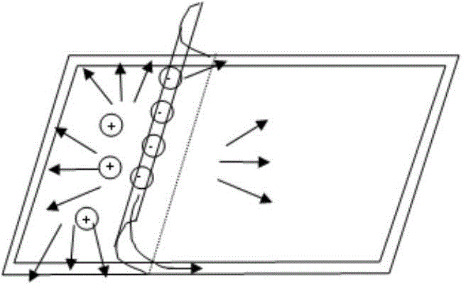
[0003] ADS display panel products tend to generate a lot of static electricity during the film tearing process. Under certain abnormal conditions, the generated static electricity cannot be quickly dissipated, which in turn causes the polarization of the liquid crystal, resulting in unrecoverable mura (that is, uneven brightness of the display, resulting in various trace phenomenon)
[0004] The existing ADS product preparation process has no special treatment for this process. Generally, the module is assembled immediately after tearing off the film, and a conductive tape (generally about 1cm wide and 1cm long, one on each side) is attached to the CF ( Color filter, Color Filter) ITO (Indium Tin Oxides, Indium Tin Oxides) is connected to the outer frame of the product, so there may be a certain degree of random defects, which increases the probability of product defects

Method used


Image

  • Polarizing plate and manufacturing method thereof and display screen
  • Polarizing plate and manufacturing method thereof and display screen
  • Polarizing plate and manufacturing method thereof and display screen

Examples


Embodiment 1

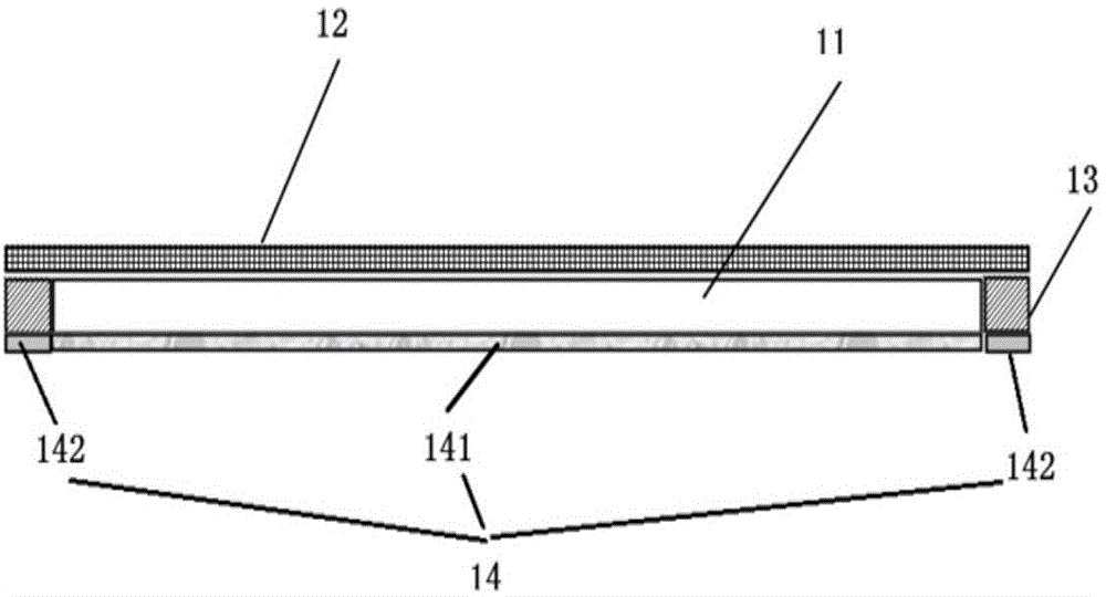
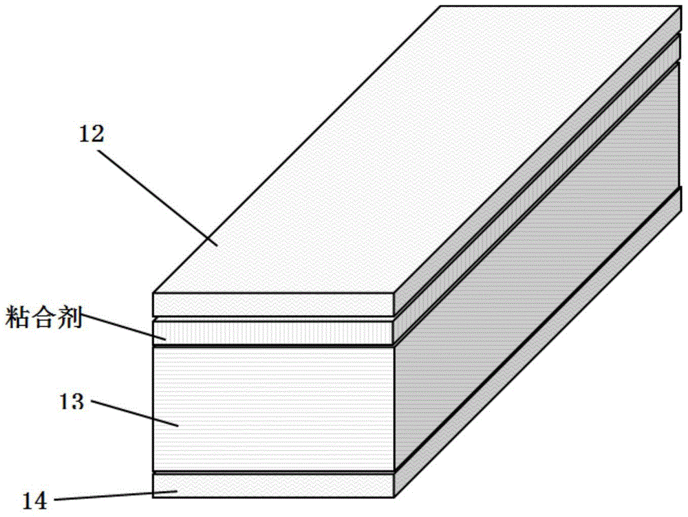
[0039] The polarizer provided by the embodiment of the present invention includes a polarizer main layer 11, a protective film layer 12, a conductive layer 13 and a release film 14, wherein: the first outer surface of the polarizer main layer 11 is coated with a protective film layer 12 ; The second outer surface of the polarizer main layer 11 is coated with a release film 14 ; the periphery of the polarizer main layer 11 is coated with a conductive layer 13 . Such as Figure 1a As shown, it is a schematic diagram of the basic structure of the polarizer provided by the embodiment of the present invention. From bottom to top, it is a release film 14, a polarizer main layer 11, a conductive layer 13 located on the periphery of the polarizer main layer 11, and a protective film layer 12. . Wherein, the release film 14 may include two parts, one part is the release film 141 in contact with the main body layer 11 of the polarizer, and the other part is the release film 142 in conta...

Embodiment 2

[0044] The polarizer provided by the embodiment of the present invention increases the conductivity of charges and increases the release path of charges through structural design. Preferably, during specific implementation, the protective film layer 12 is pasted on the main body layer 11 of the polarizer through a pressure-sensitive adhesive layer. In order to further improve the conductivity of charges, the pressure-sensitive adhesive layer of the protective film layer 12 can be a specially treated adhesive layer with good conductive diffusivity, and the adhesive layer whose conductive diffusivity parameter is greater than a preset threshold can be selected. For example, the pressure-sensitive adhesive layer can be, but not limited to, conductive polymer material, electrical network, material doped with carbon black or doped with conductive particles.

Embodiment 3

[0046] In order to further improve the conductivity of charges, a metal film is vapor-deposited on the surface of the polarizer provided in the embodiment of the present invention in contact with the protective film layer 12 . During specific implementation, any general metal film is acceptable. The metal film not only has good electrical conductivity, but also can generate polarized light through the grid structure. The grid structure of the metal film refers to a strip-shaped light leakage structure like a grating. Usually, the slits of the grating are on the order of mm (millimeters). During specific implementation, considering the difficulty of processing, preferably, the metal film may be a copper film or an aluminum film. More preferably, the polarization direction generated by the metal film grid is consistent with the polarization direction of the main layer 11 of the polarizer.

[0047] In practice, the thickness of the conductive layer 13 is the same or close to tha...


PUM


Abstract

The invention discloses a polarizing plate and a manufacturing method thereof and a display screen, and aims to prevent mura from being produced by the polarizing plate during tearing and reduce the probability of bad products. The polarizing plate comprises a polarizing plate main body layer, a protective film layer, a conductive layer and a release film, wherein the protective film layer is attached to the first outer surface of the polarizing plate main body layer; the release film is attached to the second outer surface of the polarizing plate main body layer; the conductive layer is attached to the periphery of the polarizing plate main body layer.

Description

technical field [0001] The invention relates to the technical field of liquid crystal display, in particular to a polarizer, a preparation method thereof and a display screen. Background technique [0002] ADS (Advanced Super Dimension Switch) technology is a collective name for the core technology represented by wide viewing angle technology. ADS technology is a wide viewing angle technology developed to solve large-size, high-definition desktop monitors and LCD TV applications, and it is a type of hard screen technology. ADS technology overcomes the problem of low light transmission efficiency of conventional IPS (In-Plane-Switching) technology, and achieves high light transmission efficiency under the premise of wide viewing angle. [0003] ADS display panel products tend to generate a lot of static electricity during the film tearing process. Under certain abnormal conditions, the generated static electricity cannot be quickly dissipated, which in turn causes the polari...

Claims


Application Information

Patent Timeline
Patent Type & Authority Applications(China)
IPC IPC(8): G02B5/30G02F1/1335
CPCG02B5/3041G02F1/133528G02F1/136204G02B5/3033G02F2202/22G02B1/14G02F1/133388G02F1/1335G02B5/30G02F1/133345G02F1/1337G02F1/135G02F1/136G02F2201/50G02F2202/28
Inventor 王俊伟于海峰黄海琴李东熙
Owner BOE TECH GRP CO LTD
Learn More