A rectifier cabinet for a power generation vehicle

A technology for rectifier cabinets and power generation vehicles, which is applied in the modification of electrical components and power electronics, and the conversion of AC power input into DC power output, etc. To achieve the cooling effect and other problems, to achieve the effect of increasing the natural cooling effect, easy operation, easy ventilation and heat dissipation

Inactive Publication Date: 2017-01-25
CHANGZHOU UNIV
View PDF4 Cites 0 Cited by
  • Summary
  • Abstract
  • Description
  • Claims
  • Application Information

AI Technical Summary

Problems solved by technology

[0002] The three-phase AC460V power generated by the diesel generator of the 25T / G rail car power generation car, after the controllable rectification of the rectifier cabinet, outputs a DC 600V power supply for the load on the rail car. In order to meet the needs, the rectifier cabinet needs to have two sets Independent power supply system and rectification system, and the main circuit and control circuit need to be completely independent without interfering with each other. At present, rectifier cabinets mostly use three-phase fully-controlled thyristor bridge rectifier devices, and filter circuits and related control circuits are equipped on the DC side of the rectifier module. , protection circuit, etc. These rectification devices and circuits are all arranged in the same cabinet, resulting in chaotic structure of the control circuit and power circuit, crowded space, and great potential safety hazards in daily inspection and maintenance.
In addition, because most of the rectifier cabinets are high-power components, the current passing through them is relatively large, so the components generate heat. In order to ensure and improve the heat dissipation effect of the rectifier cabinet, the upper air inlet and lower air outlet or side air outlet are mostly used at present, but It is still difficult to achieve the ideal cooling effect
At the same time, during the hoisting and transportation of the rectifier cabinet, the existing schemes mostly use wooden pallets, ropes, etc., which increase manpower and material resources and have great safety hazards

Method used


Image

  • A rectifier cabinet for a power generation vehicle
  • A rectifier cabinet for a power generation vehicle
  • A rectifier cabinet for a power generation vehicle

Examples


Embodiment

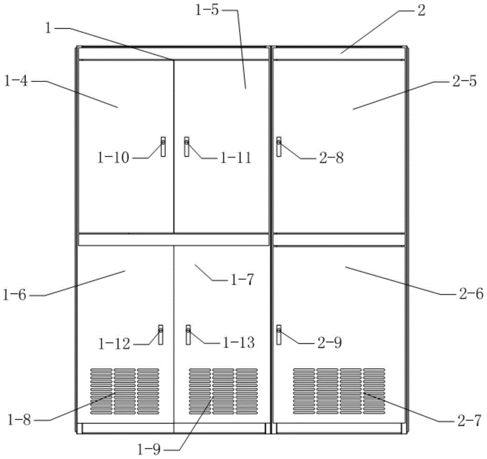
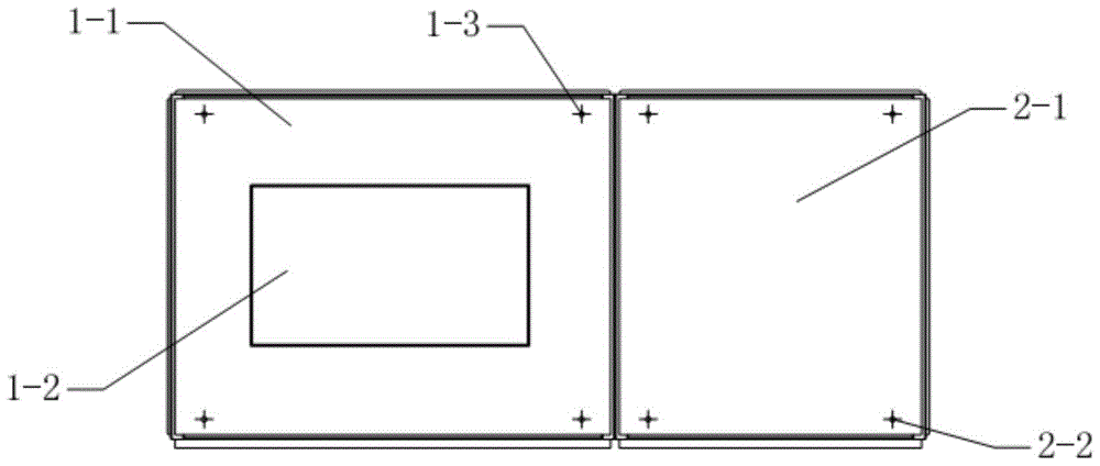
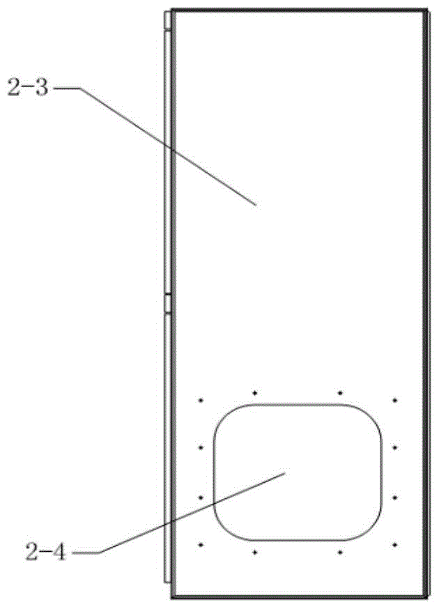
[0030] Such as Figure 1 ~ Figure 4As shown, a rectifier cabinet for a power generation vehicle of the present invention includes a rectifier box 1 and a control box 2, the rectifier box 1 and the control box 2 are arranged side by side, and the rectifier box 1 and the control box 2 are connected by hexagon bolt The two cabinets are fixed into one cabinet, and there is no sealing plate between the two cabinets.

[0031] The rectifier box 1 includes a rectifier box upper sealing plate 1-1, an upper vent 1-2, a rectifier box lifting ring screw 1-3, a rectifier box upper left door panel 1-4, a rectifier box right upper door panel 1-5, a rectifier box left lower door panel 1-6, right lower door panel of rectifier box 1-7, shutter of left lower door panel of rectifier box 1-8, shutter of right lower door panel of rectifier box 1-9, left upper door handle and door lock assembly of rectifier box 1-10, right upper door handle of rectifier box And door lock assembly 1-11, rectifier bo...


PUM


Abstract

A rectifying cabinet for a power generating car comprises a rectifying box and a control box. The rectifying box and the control box are arranged side by side from left to right; the rectifying box comprises an upper sealing plate, an upper ventilation opening, a lifting bolt, an upper left door plate, an upper right door plate, a lower left door plate, a lower right door plate, a lower left door plate louver, a lower right door plate louver, an upper left door plate handle and door lock assembly, an upper right door plate handle and door lock assembly, a lower left door plate handle and door lock assembly, a lower right door plate handle and door lock assembly, a rear sealing plate, a left sealing plate, a framework and a lateral beam; a thyristor bridge type rectifying device and a high-power device are distributed in the rectifying box; the control box comprises a control box upper sealing plate, a control box lifting bolt, a control box right sealing plate, a lateral air outlet, a control box upper door plate, a control box lower door plate, a control box lower door plate louver, a control box upper door plate handle and door lock assembly, a control box lower door plate handle and door lock assembly, a control box rear sealing plate, a framework and a lateral beam; a filtering circuit, a control circuit and a protecting circuit are distributed in the control box.

Description

technical field [0001] The invention relates to a rectification device, in particular to a novel rectification cabinet for rail passenger car power generation vehicles. Background technique [0002] The three-phase AC460V power generated by the diesel generator of the 25T / G rail car power generation car, after the controllable rectification of the rectifier cabinet, outputs a DC 600V power supply for the load on the rail car. In order to meet the needs, the rectifier cabinet needs to have two sets Independent power supply system and rectification system, and the main circuit and control circuit need to be completely independent without interfering with each other. At present, rectifier cabinets mostly use three-phase fully-controlled thyristor bridge rectifier devices, and filter circuits and related control circuits are equipped on the DC side of the rectifier module. , protection circuit, etc. These rectification devices and circuits are all arranged in the same cabinet, r...

Claims


Application Information

Patent Timeline
Patent Type & Authority Patents(China)
IPC IPC(8): H02M7/00H05K7/20
CPCH02M7/00H05K7/20909
Inventor 万玉山陈艳秋黄利方慧
Owner CHANGZHOU UNIV
Why Eureka
Try Eureka