Cage for inclined ball bearing

A technology for cages and rolling bearings, applied to ball bearings, bearings, bearing components, etc., can solve the problems of increased waste, logistics problems, etc., and achieve the effect of high load capacity and small axial width

Active Publication Date: 2015-05-20
SCHAEFFLER TECH AG & CO KG
View PDF10 Cites 4 Cited by
  • Summary
  • Abstract
  • Description
  • Claims
  • Application Information

AI Technical Summary

Problems solved by technology

This is achieved at the expense of the stability of the cage and also leads to logistical problems, that is, in the case of a large accumulation leads to the hooking of only one-sided reinforced rings
This often results in increased scrap, especially when cages are shipped as loose parts

Method used


Image

  • Cage for inclined ball bearing
  • Cage for inclined ball bearing

Examples


Embodiment Construction

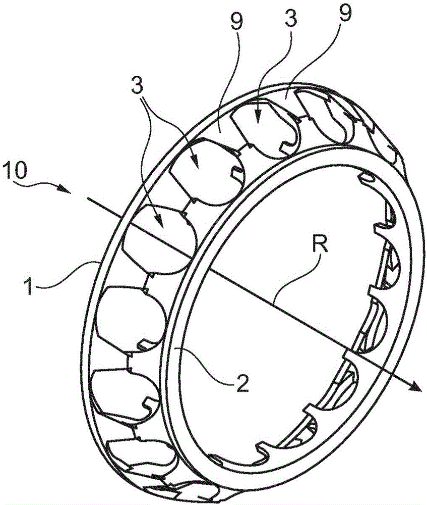
[0025] figure 1 A radial thrust ball bearing cage 10 with an axis of rotation R is shown. The ball pockets 3 are separated by webs 9 , wherein the webs 9 also connect the rings 1 , 2 to each other and provide sufficient stability.

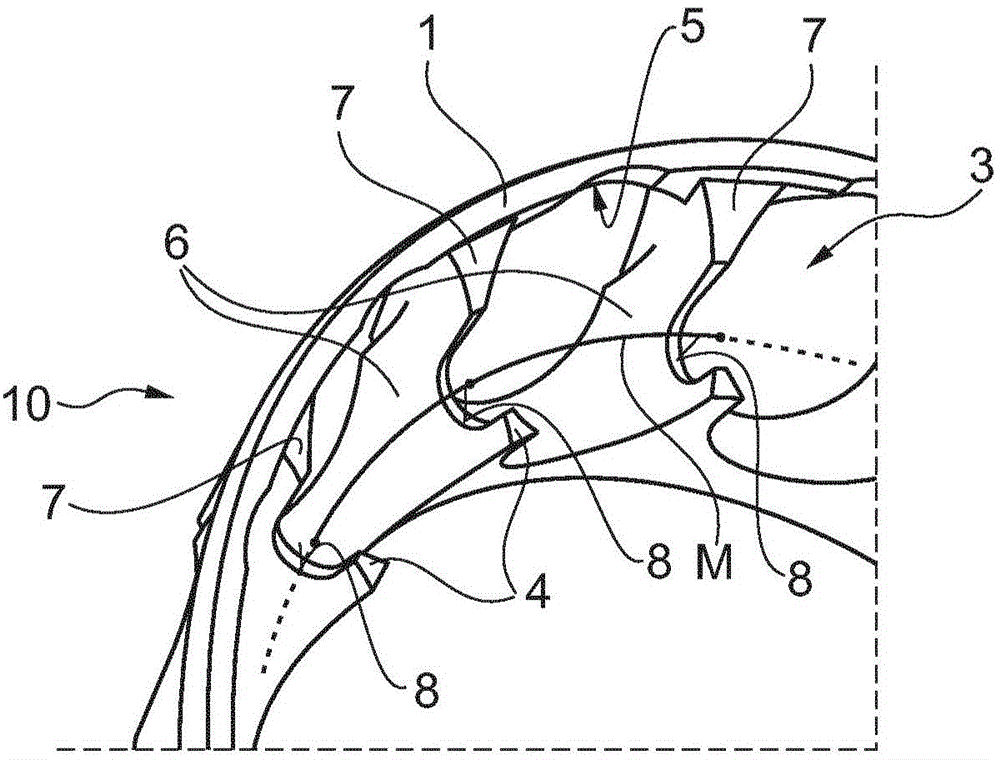
[0026] figure 2 A section of the radial thrust ball bearing cage 10 is shown, wherein the region of the fork 8 around the three webs 9 can be seen more precisely. The free end 4 together with the first end 7 of the web 9 forms the desired fork 8 . The fork 8 is open in an axial direction directed towards the first ring 1 . This characteristic leads to the logistical advantage that cages of the same size can be stacked in a staggered manner, wherein the second ring 2 of the cage is inserted into the fork 8 of the adjacent cage.

[0027] Furthermore, the rings are overall designed in such a way that they do not catch on each other and can therefore be easily detached. This characteristic is mainly based on the construction of the first ring.

...


PUM


Abstract

In summary, the invention relates to a rolling bearing cage 10 with two rings 1, 2 connected by webs 9, wherein webs 9 provided with bifurcations 8 are used to solve the problem of reducing weight while simultaneously ensuring increased load rating, wherein said webs 9 permit adjacent rolling bodies to be arranged very close to one another. Furthermore, a plurality of identical cages 10 are prevented from tangling in each other when said cages are heaped in large quantities. Overall, the cage 10 allows a more compact design for inclined ball bearings and also reduces their moment of friction.

Description

technical field [0001] The invention relates to a rolling bearing cage for receiving rolling bodies designed as balls, the rolling bearing cage having two axially opposite rings and webs forming rolling body pockets together with the rings, wherein the first The first central circular diameter of the ring is larger than the second central circular diameter of the second ring and also larger than the central circular diameter of the rolling bodies. Furthermore, the invention relates to a rolling bearing, in particular a radial thrust ball bearing, having one or more such cages. Background technique [0002] Rolling-element cages of this type are frequently found in radial thrust ball bearings, such as, for example, double row radial thrust ball bearings. The rolling bearing cage has the task of arranging the spherical rolling bodies arranged and guided therein so that they are spaced apart from one another in such a way that a high load capacity can be achieved due to optimi...

Claims


Application Information

Patent Timeline
Patent Type & Authority Applications(China)
IPC IPC(8): F16C19/16F16C33/38
CPCF16C19/163F16C33/3856F16C33/3887F16C2326/02F16C33/3843F16C19/16F16C33/38F16C33/3862
Inventor 拉尔夫·海斯弗兰克·艾歇尔曼费利克斯·格斯纳
Owner SCHAEFFLER TECH AG & CO KG
Why Eureka
Try Eureka